Accurate Analysis: A Comprehensive Guide to Solvent Background Correction in UV-Vis Spectroscopy
This article provides researchers, scientists, and drug development professionals with a complete framework for implementing effective solvent background correction in UV-Vis spectroscopy.
Accurate Analysis: A Comprehensive Guide to Solvent Background Correction in UV-Vis Spectroscopy
Abstract
This article provides researchers, scientists, and drug development professionals with a complete framework for implementing effective solvent background correction in UV-Vis spectroscopy. It covers the foundational principles of why background absorption occurs and its impact on data integrity, details step-by-step methodological approaches for reliable blank measurement and baseline correction, addresses common troubleshooting scenarios for optimal results, and presents advanced validation techniques to ensure method robustness. By synthesizing current best practices and novel fitting approaches, this guide aims to enhance the accuracy and reliability of quantitative analyses in biomedical research, from characterizing hemoglobin-based oxygen carriers to ensuring precise nucleic acid and protein quantification.
Why Solvent Background Matters: Principles and Consequences for Spectral Accuracy
Troubleshooting Guides and FAQs
Why am I getting inconsistent absorbance readings or a drifting baseline?
Inconsistent readings and baseline drift are common issues often linked to instrument stability and sample handling.
- Allow for proper instrument warm-up: Let the spectrophotometer stabilize for 20-30 minutes after turning it on, especially tungsten halogen or arc lamps, to allow the light source output to stabilize [1] [2].
- Check and replace the light source: Aging or faulty lamps (deuterium for UV, tungsten for visible) can cause fluctuations and should be replaced per the manufacturer's schedule [1] [3].
- Perform regular calibration: Calibrate the instrument regularly using certified reference standards. Always perform a baseline correction with the correct blank solution before measuring samples [1] [3].
- Ensure sample temperature stability: Temperature fluctuations can affect absorbance readings, particularly for temperature-sensitive samples [2].
My blank measurement fails. What should I check?
A blank measurement error typically indicates a problem with the reference or its interaction with the instrument.
- Use the correct reference solution: Always re-blank with the exact solvent or buffer used to prepare your sample. For bacterial cultures, use the sterile culture media as the reference [1] [4].
- Inspect the reference cuvette: Ensure the cuvette used for the blank is perfectly clean, free of scratches, smudges, and residue. Handle cuettes with gloves or lint-free tissues to avoid fingerprints [1] [3] [2].
- Verify cuvette orientation and filling: Make sure the cuvette is correctly aligned in the holder and that it is filled with enough solution so the light beam passes through the liquid, not the air [2].
- Check for software settings: Ensure the instrument's firmware is up to date and that the software settings match your chosen test method [1].
How can I tell if my sample or cuvette is contaminated?
Unexpected peaks, a noisy signal, or generally poor data quality can often be traced back to contamination.
- Inspect and clean cuvettes thoroughly: Before use, wash cuvettes meticulously. Any residue from previous experiments can introduce unexpected peaks [2].
- Review sample preparation steps: Contamination can be introduced during cleaning, decanting materials, or dissolving your sample. Use high-purity, spectrophotometric-grade solvents to avoid impurities that absorb light [3] [2].
- Check for air bubbles: Bubbles trapped in the sample can scatter light and cause erroneous readings. Degas solutions or gently tap the cuvette to remove trapped air [3].
- Ensure proper cuvette material: Using a plastic cuvette with an incompatible solvent can dissolve the plastic, contaminating the sample and damaging the cuvette [2].
What is causing high background noise or unexpected absorption?
High background often stems from the intrinsic properties of the materials used or from light scattering.
- Select the appropriate cuvette material: Standard glass and plastic cuvettes absorb UV light below 300-400 nm. For UV measurements below 300 nm, such as nucleic acid or protein analysis, you must use quartz cuvettes, which are transparent down to 190 nm [4] [5].
- Minimize stray light: Use high-quality optical filters and ensure the sample compartment is closed to prevent ambient light interference. Calibrating against potassium chloride (KCl) for the UV range can help identify stray light issues [3].
- Reduce light scattering: For turbid samples or solutions with high particulate concentrations, light scattering can increase the background signal. Filter samples or centrifuge to remove particulates, or consider diluting the sample if appropriate [6].
- Correct for solvent absorption: If your solvent has significant absorption in your measurement range, placing the same solvent in the reference beam path can improve the signal-to-noise ratio and dynamic range [7].
Experimental Protocols
Detailed Methodology: Assessing and Correcting for Cuvette-Generated Interference
This protocol provides a step-by-step method to identify and account for background signals introduced by the cuvette itself.
Objective
To determine the absorbance contribution of the cuvette and ensure it does not interfere with sample measurements.
Materials
- Spectrophotometer (UV-Vis)
- Matching quartz cuvettes (e.g., 10 mm path length)
- High-purity solvent (e.g., HPLC-grade water)
- Lint-free wipes or gloves
- Micropipettes and tips
Procedure
- Instrument Preparation: Turn on the spectrophotometer and allow the lamp to warm up for at least 20-30 minutes to stabilize [2].
- Baseline Correction (Air-to-Air): With the sample compartment empty, perform a baseline correction. This records the instrument's baseline with no cuvette present [7].
- Cuvette Blank Measurement:
- Thoroughly clean a quartz cuvette according to the guidelines in the "Research Reagent Solutions" table.
- Fill the cuvette with the high-purity solvent you will use for your sample preparation.
- Carefully place the cuvette in the holder, ensuring proper alignment of the optical windows.
- Run a blank measurement. This spectrum represents the combined signal of the solvent and the cuvette.
- Data Interpretation: The resulting absorbance spectrum is your system blank. Any absorbance peaks or elevated baselines in your sample measurements must be evaluated against this blank.
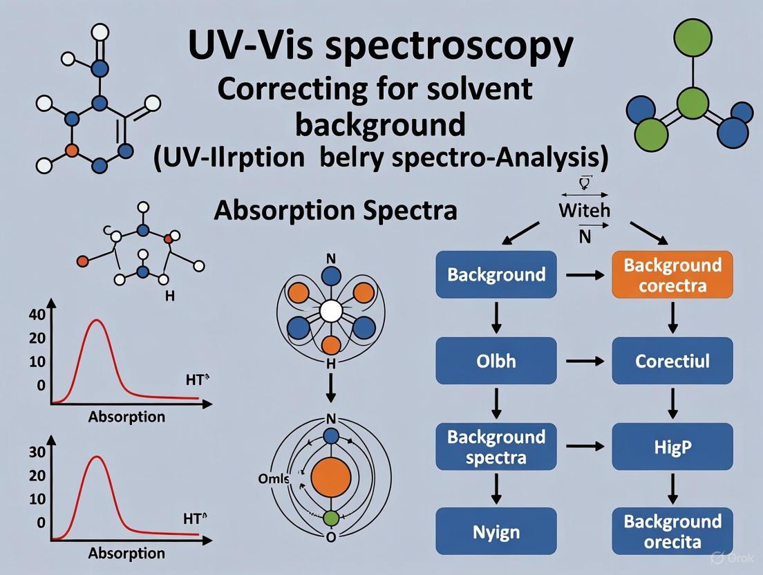
Workflow for Systematic Solvent Background Correction
This workflow outlines the logical process for identifying and managing different sources of interference in your spectra.
Research Reagent Solutions
The following table details essential materials for managing solvent background in UV-Vis spectroscopy.
| Item | Function & Rationale | Key Specifications |
|---|---|---|
| Quartz Cuvettes (Fused Silica) | Holds liquid sample; essential for UV transparency down to ~190 nm, chemical resistance, and low autofluorescence [4] [5]. | - Path length: 10 mm (standard)- Windows: 2 for absorbance, 4 for fluorescence- Transparency range: 190-2500 nm |
| Spectrophotometric-Grade Solvents | Dissolves analytes; high purity minimizes background absorption from impurities. Common choices: water (cutoff ~190 nm), methanol (~205 nm), acetonitrile (~190 nm) [3] [6]. | - Low UV cutoff- High purity grade (HPLC/spectrophotometric)- Compatible with sample and cuvette |
| Syringe Filters (PTFE Membrane) | Removes particulates from samples; reduces light scattering that causes high background noise and signal instability [6]. | - Pore size: 0.45 µm or 0.2 µm- Material: PTFE for chemical inertness- Low analyte binding |
| Certified Reference Materials (CRMs) | Validates instrument accuracy and blanking procedure; materials with known absorbance values confirm the entire measurement system is performing correctly [3]. | - Precisely known absorbance values- e.g., Holmium oxide filters for wavelength accuracy |
Data Presentation: Cuvette Material Properties
The table below summarizes the critical properties of common cuvette materials to guide appropriate selection and highlight sources of interference.
| Feature | Quartz (Fused Silica) | Optical Glass | Plastic (PS/PMMA) |
|---|---|---|---|
| UV Transmission | Excellent (190–2500 nm) [5] | Limited (>320 nm) [5] | Not supported (blocks UV) [5] |
| Autofluorescence | Low [5] | Moderate [5] | High [5] |
| Chemical Resistance | High (avoids degradation from most solvents) [5] | Moderate (degrades with strong acids/bases) [5] | Low (attacked by acetone, ethanol, DMSO) [5] |
| Max Temperature | 150–1200 °C [5] | ≤90 °C [5] | ≤60 °C [5] |
| Best Use | UV-Vis, fluorescence, solvent analysis [5] | Visible-light assays only [5] | Teaching, disposable colorimetric assays [5] |
Why is my calculated sample concentration consistently higher than expected?
An uncorrected baseline, resulting from the failure to properly zero the instrument using a blank solution, is a direct cause of concentration overestimation. The blank solution accounts for the absorbance from the solvent, cuvette, and other background elements. When you do not subtract this background signal, the instrument attributes all measured absorbance to your target analyte. This inflates the absorbance value, which, through the Beer-Lambert law, leads to an incorrectly high concentration calculation [4] [8].
This guide will help you troubleshoot and resolve this specific issue.
Troubleshooting Guide: Uncorrected Baseline
Symptom: Absorbance readings are positive even when the sample is replaced with pure solvent.
| Possible Cause | Diagnostic Steps | Corrective Actions |
|---|---|---|
| No Blank Measurement [8] | Check if the instrument was zeroed (or blanked) before measuring the sample. | Always zero the spectrophotometer using a matched blank solution before analyzing samples [8]. |
| Contaminated Cuvette [2] | Visually inspect the cuvette for scratches, dust, or residue. Clean the cuvette and re-measure the blank. | Thoroughly clean cuvettes with appropriate solvents. Handle only with gloved hands to avoid fingerprints [2]. |
| Contaminated Blank Solution [2] | Prepare a fresh batch of blank solution from clean, high-purity solvents. | Ensure all solvents and buffers are free of contaminants and do not absorb significantly in your wavelength range [8]. |
| Instrument Drift [8] | Re-measure the blank solution after a period of operation. If the baseline has shifted, drift may be the issue. | Allow the lamp to warm up for the recommended time (~20 mins for tungsten/halogen) [2]. Re-calibrate the baseline periodically during long sessions [8]. |
| Using an Inappropriate Blank | Verify that the blank is chemically identical to your sample's solvent matrix, just without the analyte. | If your sample is in an aqueous buffer, the blank should be the same aqueous buffer [4]. |
Symptom: Calibration curves have a positive y-intercept, indicating non-zero absorbance at zero concentration.
This symptom is a classic sign of a consistent background error. The causes and solutions are the same as those listed in the table above. A systematic baseline shift will manifest as a positive y-intercept, confirming that your concentration calculations are skewed from the start.
Frequently Asked Questions
What exactly is a "blank" solution?
A blank solution is a reference that contains all the components of your sample solution except for the analyte you want to measure [4]. Its purpose is to establish a baseline absorbance level, which the instrument then subtracts from your sample reading to report the true absorbance of the analyte.
Can I use water as a blank if my sample is in a buffer?
No. You must use the same buffer as your sample as the blank. If you use water to blank a sample in buffer, you are not accounting for the absorbance of the buffer itself, which will lead to an overestimation of your analyte's concentration [4] [9].
My blank reads zero, but my concentrations are still off. What else could it be?
While an uncorrected baseline is a primary cause of overestimation, other issues can contribute to inaccuracy:
- Stray Light: This is light of unwanted wavelengths reaching the detector, which can cause inaccurate readings, particularly at high absorbances [10] [11].
- Instrument Linearity: Absorbance values are most reliable within a certain range (typically 0.1 to 1.0 AU). Values above 1.0 can become non-linear due to instrument limitations, violating the Beer-Lambert law [4] [12]. If your sample is too concentrated, dilute it.
- Dirty or Scratched Cuvettes: These can scatter light, increasing the apparent absorbance of both the blank and sample and leading to unpredictable errors [8].
Experimental Protocol: Proper Baseline Correction
To ensure accurate concentration measurements, follow this methodology:
- Prepare the Blank: Prepare your blank solution with high precision, ensuring it is chemically identical to your sample's solvent [4].
- Instrument Warm-up: Turn on the spectrophotometer and allow the light source to warm up for the manufacturer's recommended time (often 20-30 minutes) to ensure stable output [2].
- Zero the Instrument:
- Place the blank solution into a clean, matched cuvette.
- Insert the cuvette into the sample holder and close the lid.
- Command the instrument to "Set Zero" or "Blank."
- Measure Sample: Replace the blank cuvette with your sample cuvette and measure the absorbance. The value displayed is now the absorbance due to your analyte alone.
- Periodic Re-checking: Re-check the blank reading periodically (e.g., every 5-10 samples) to monitor and correct for any instrument drift [8].
Workflow Visualization
The following diagram illustrates the logical relationship between correct and incorrect blanking procedures and their outcomes.
The Scientist's Toolkit: Essential Research Reagents & Materials
| Item | Function in UV-Vis Spectroscopy |
|---|---|
| High-Purity Solvents (e.g., HPLC-grade water, solvents) | To prepare samples and blanks with minimal UV-Vis absorbance of their own, ensuring a low background signal [8]. |
| Matched Quartz Cuvettes | To hold samples and blanks. Quartz is transparent across UV and visible wavelengths. Using a "matched" set ensures path length consistency [4] [2]. |
| Buffer Salts & Reagents | To maintain a stable pH environment for the analyte, which can prevent shifts in the absorption spectrum [8]. |
| Potassium Dichromate / Holmium Oxide | Certified reference materials used for instrument validation and calibration checks of wavelength accuracy and photometric linearity [10] [8]. |
| Standard Cuvette Cleaning Kit (e.g., solvents, lint-free wipes) | To ensure cuvettes are free of contaminants that could scatter light or contribute to absorbance, which is critical for an accurate baseline [2] [8]. |
FAQs on Reference and Blank Measurements
1. What is the purpose of a blank measurement? The primary purpose of a blank measurement is to zero the instrument, establishing a baseline absorbance of zero for your solvent or matrix. This corrects for any light absorption caused by the solvent itself, the cuvette, or any suspended particles, ensuring that the final spectrum reflects only the analyte of interest [9] [13].
2. My blank measurement fails or gives an error. What should I check? A blank measurement error often points to issues with the reference solution or the cuvette. First, ensure you have used the correct pure solvent or buffer for your specific experiment. Then, inspect the cuvette for residue, scratches, or fingerprints, and clean it thoroughly with an appropriate solvent. Finally, confirm that the cuvette is properly aligned in the sample holder and that the path length is correct [14].
3. Why is my absorbance reading unstable or drifting after using the blank? Unstable readings after blanking can be caused by several factors. These include air bubbles in the sample, a dirty cuvette, or evaporation of the solvent over time, which changes the concentration. Ensure your sample is free of bubbles, the cuvette is clean, and the chamber is covered to prevent evaporation [15] [2].
4. Do I always need to place a solvent-filled cuvette in the reference beam? Not necessarily. Modern double-beam spectrophotometers are designed to perform a baseline correction computationally, making it unnecessary to place a solvent cell in the reference beam path; an "air/air" measurement is often sufficient [7]. However, if the solvent itself has significant absorption in the wavelength range of interest, placing a matched cuvette filled with solvent in the reference beam will improve measurement dynamic range and signal-to-noise ratio [7].
5. How often should I re-run the blank measurement? It is good practice to run a fresh blank measurement whenever you change solvents, switch to a different cuvette, or after a significant period of time (e.g., every 30-60 minutes) to correct for any potential instrumental drift [13] [14].
Troubleshooting Guide for Blank-Related Issues
The following table outlines common problems, their potential causes, and solutions related to blank measurements.
| Problem Observed | Potential Causes | Recommended Solutions |
|---|---|---|
| High Blank Absorbance | Contaminated solvent; Dirty or scratched cuvette; Incorrect solvent for wavelength range [2] [13]. | Use high-purity solvents; Meticulously clean or replace cuvettes; Ensure solvent is transparent in your analytical range [16]. |
| Erratic Baseline/Noise | Air bubbles in the light path; Unstable light source (lamp not warmed up); High sample turbidity [2] [14]. | Tap cuvette to dislodge bubbles; Allow lamp warm-up (20+ mins for halogen/arc lamps) [2]; Filter or centrifuge sample to remove particles [17]. |
| Non-Linearity in Calibration | Sample absorbance too high (>1.2 AU); Stray light; Incorrect blank [17] [13]. | Dilute sample to ideal range (0.1-1.0 AU) [17] [15]; Use instrument with low stray light; Verify blank is correct [13]. |
| Negative Absorbance Readings | Blank has higher absorbance than sample; Condensation on cold cuvettes; Incorrect blank zeroing [2]. | Ensure blank and sample use same solvent and cuvette; Wipe cuvette exterior dry; Re-zero instrument with fresh blank [13]. |
Experimental Protocol: Executing a Valid Blank Measurement
This protocol provides a detailed methodology for establishing a correct baseline in UV-Vis spectroscopy, a critical step for quantitative analysis.
Objective To correctly zero the spectrophotometer using a blank solution that accounts for all sources of absorption and scattering except for the target analyte.
Materials and Equipment
- UV-Vis Spectrophotometer (single or double beam)
- Matched cuvettes (e.g., quartz for UV, optical glass or plastic for visible light)
- High-purity solvents (e.g., HPLC-grade water, spectro-grade hexane)
- Pipettes and volumetric flasks
- Lint-free wipes (e.g., Kimwipes)
Step-by-Step Procedure
- Preparation: Turn on the spectrophotometer and allow the lamp to warm up for at least 20 minutes to stabilize the light output [2].
- Cuvette Handling: Using gloves, handle the cuvette only by its opaque sides to prevent fingerprints. Clean the transparent sides with a lint-free wipe.
- Blank Solution: Fill the cuvette with the same pure solvent or buffer used to prepare your sample solution.
- Loading: Place the blank-filled cuvette into the sample holder, ensuring a consistent orientation (e.g., align the marked side). Close the lid.
- Instrument Zeroing: Initiate the "Auto Zero" or "Blank" function on the instrument. This sets the absorbance to 0.000 AU (and %Transmittance to 100%) across the selected wavelength range.
- Sample Measurement: Remove the blank cuvette. Replace it with your sample cuvette and proceed with the measurement. The displayed absorbance is now corrected for the solvent and cuvette.
Data Interpretation Notes
- A properly zeroed baseline should be flat and close to zero absorbance across the wavelength range of interest.
- Any significant curvature or offset in the baseline of your sample spectrum suggests an issue with the blank measurement or sample preparation [17].
Workflow of a Blank Measurement
The following diagram illustrates the logical sequence and decision points for correctly performing a blank measurement in UV-Vis spectroscopy.
The Scientist's Toolkit: Essential Materials for Reliable Blank Measurements
| Item | Function & Importance |
|---|---|
| Quartz Cuvettes | Ideal for UV-Vis range (190-1100 nm) due to high transparency. Essential for UV measurements below 350 nm [2]. |
| Spectrophotometric-Grade Solvents | High-purity solvents with minimal UV absorption. Critical for ensuring the blank does not contribute significant background signal [13]. |
| Lint-Free Wipes | For cleaning cuvettes without introducing fibers or scratches, which can scatter light and cause errors [13]. |
| Certified Reference Materials | Used for periodic instrument calibration to verify wavelength and photometric accuracy, ensuring the entire system is validated [17] [18]. |
| Cuvette Holder (Thermostatic) | Maintains consistent sample temperature, preventing baseline drift caused by temperature-sensitive solvent properties or reactions [13]. |
In UV-Vis spectroscopy, accurate measurement relies on separating the sample's absorbance from background interference. A primary source of this interference is the cuvette itself. While all materials will interact with light to some degree, their behavior in the ultraviolet (UV) range is vastly different. Selecting the wrong cuvette material is a common experimental error that can lead to failed experiments, corrupted data, and incorrect conclusions, particularly when working below 350 nm or when correcting for solvent background. This guide details the fundamental properties of quartz, glass, and plastic to enable informed material selection for reliable spectroscopic results.
Core Concepts: Transmission and Material Limitations
The Science of UV Transmission
Ultraviolet-Visible (UV-Vis) spectroscopy analyzes how molecules absorb light from the ultraviolet (typically 190-400 nm) to the visible (400-800 nm) regions of the electromagnetic spectrum [9] [16]. The core measurement, absorbance (A), is governed by the Beer-Lambert Law: A = εbc, where ε is the molar absorptivity, b is the path length, and c is the concentration [9].
For a measurement to be accurate, the recorded absorbance must come almost exclusively from the sample. The cuvette must therefore be transparent—it must transmit light without significant absorption or scattering across the wavelengths of interest. Transmittance (T) is defined as the ratio between the intensity of radiation transmitted through a material and the incident radiation [19]. Any absorption by the cuvette material contributes to the background "noise," reducing the signal-to-noise ratio and compromising data integrity, especially in low-absorbance samples.
Why Materials Behave Differently in the UV Spectrum
The atomic and molecular structure of a material dictates its optical properties. Transparency in the UV region requires that the material's electrons cannot be excited by the high energy of UV photons.
- Quartz (Fused Silica) is a high-purity, synthetic, or natural form of silicon dioxide (SiO₂) with a highly regular and stable molecular structure. This structure requires high-energy, short-wavelength photons (below ~190 nm) to excite its electrons, making it transparent throughout the UV, Visible, and near-Infrared (NIR) spectrum [20] [21].
- Glass is also composed primarily of SiO₂ but includes other metal oxide impurities (e.g., sodium, calcium). These additives create defects in the molecular matrix. These defects have electrons that can be excited by lower-energy UV photons, causing the material to absorb strongly at shorter UV wavelengths [22] [21].
- Plastics (e.g., PMMA, Polystyrene) are organic polymers with complex molecular structures and additives. The carbon-carbon and carbon-hydrogen bonds in these polymers, along with additives used in their manufacture, are highly effective at absorbing UV radiation, making most plastics opaque to UV light [22] [23].
Comparative Analysis: Quartz vs. Glass vs. Plastic
The following table synthesizes quantitative and qualitative data to provide a clear comparison of cuvette materials.
Table 1: Comprehensive Comparison of Cuvette Material Properties
| Property | Quartz (Fused Silica) | Optical Glass | Plastic (PMMA/PS) |
|---|---|---|---|
| UV Transmission Range | Excellent down to ~190 nm [20] [21] | Cuts off below ~300-340 nm [22] [21] | Cuts off below ~380-400 nm [22] [21] |
| Transmission at 220 nm | 80% - 92% [22] | 10% - 30% [22] | < 5% [22] |
| Transmission at 260 nm (DNA) | >90% [21] | Low to Zero [21] | Zero [21] |
| Visible Transmission | Excellent | Excellent | Good |
| Autofluorescence | Very Low [21] | Moderate [21] | High [21] |
| Chemical Resistance | High (resists most acids and solvents; attacked by HF) [21] | Moderate (degrades with strong bases) [21] | Low (attacked by many organic solvents) [21] |
| Max Temperature | 150-1200°C (depending on grade) [21] | ~90°C [21] | ~60°C [21] |
| Durability & Reusability | High (years with proper care) [20] | Moderate (months to years) [21] | Low (disposable, single-use) [21] |
| Relative Cost | High | Mid | Low |
Table 2: Performance in Common UV-Based Assays
| Application | Quartz | Glass | Plastic |
|---|---|---|---|
| Nucleic Acid Quantification (260 nm) | Essential - High accuracy [22] | Not Suitable - Absorbs light | Not Suitable - Absorbs light |
| Protein Analysis (280 nm) | Essential - High accuracy [21] | Not Suitable - Absorbs light | Not Suitable - Absorbs light |
| UV-Vis Spectroscopy (full spectrum) | Ideal - Full spectrum capability [21] | Limited - Visible & NIR only | Limited - Visible only |
| Fluorescence Spectroscopy | Ideal - Very low background [21] | Poor - Moderate autofluorescence | Unsuitable - High autofluorescence |
| Colorimetric Assays (Visible) | Suitable | Ideal - Cost-effective | Ideal - Disposable |
| Studies with Organic Solvents | Ideal - Chemically resistant [21] | Suitable (with caution) | Not Suitable - Often dissolves |
Experimental Protocol: Validating Cuvette Suitability and Correcting for Background
A critical step in any UV-Vis experiment is to account for all sources of absorbance not originating from your target analyte. This includes the cuvette and the solvent.
Methodology for Background Correction:
- Prepare the Blank: Fill your cuvette with the pure solvent that your sample is dissolved in (e.g., water, ethanol, buffer).
- Collect Baseline Spectrum: Place the solvent-filled cuvette in the spectrophotometer and record an absorbance spectrum across your desired wavelength range. This measurement captures the combined background signal from the solvent and the cuvette walls.
- Measure the Sample: Replace the solvent with your sample solution and record its absorbance spectrum.
- Software Correction: Modern spectrophotometer software will automatically subtract the blank baseline spectrum from the sample spectrum. The resulting data represents the absorbance due to the analyte alone.
Troubleshooting Tip: If your baseline absorbance is unexpectedly high (e.g., >0.1 A) at your wavelength of interest, your cuvette material is likely inappropriate. For example, a high baseline at 260 nm indicates your cuvette is absorbing light and is unsuitable for DNA/RNA work.
Decision Guide: Selecting a Cuvette for an Experiment
The Scientist's Toolkit: Essential Research Reagents & Materials
Table 3: Key Materials for UV-Vis Spectroscopy
| Item | Function & Rationale |
|---|---|
| Quartz Cuvette (2-window) | The standard for UV-Vis absorbance measurements. Two optically clear windows for the light path; frosted sides for safe handling. |
| Quartz Cuvette (4-window) | Essential for fluorescence assays. All four sides are polished to allow for excitation light and 90-degree detection of emitted light. |
| HPLC-Grade Solvents | Used for preparing samples and blanks. High purity ensures minimal UV absorbance from solvent impurities. |
| Cuvette Cleaning Solution | Mild detergent or specific acid/base baths (compatible with quartz) to remove contaminants without damaging optical surfaces. |
| Lint-Free Wipes | For drying and handling cuvettes without scratching or leaving fibers on optical windows. |
Frequently Asked Questions (FAQs)
1. My budget is limited. Can I use glass cuvettes for DNA quantification at 260 nm? No. Glass begins to absorb UV light significantly below 340 nm and is nearly opaque at 260 nm [22] [21]. Using a glass cuvette will result in a very weak or non-existent signal, rendering your quantification inaccurate. Quartz is essential for this application.
2. How should I properly clean and store my quartz cuvettes to maintain their performance? Always handle cuvettes by the frosted sides. Rinse thoroughly with the solvent used in your next experiment or with purified water. For deep cleaning, use an ultrasonic cleaner or a mild detergent, avoiding abrasive cleaners. For stubborn contaminants, consult compatibility charts before using acids (except HF, which dissolves quartz) [20] [21]. Store clean and dry cuvettes in their original protective cases.
3. I see "UV-Transparent" plastic cuvettes advertised. Are these a suitable alternative to quartz? These plastics are typically transparent only down to about 300-350 nm, which is insufficient for critical applications like nucleic acid quantification at 260 nm [22] [21]. They may be suitable for some protein work at 280 nm, but their higher autofluorescence and poor solvent resistance make them a poor choice for fluorescence or general UV work compared to quartz.
4. Why does correcting for solvent background also correct for the cuvette? When you run a blank, you are measuring the baseline absorbance of everything in the light path besides your sample. This includes the solvent and the cuvette walls. When the software subtracts this blank spectrum, it removes the signal contribution from both, isolating the absorbance of your analyte.
Technical Support Center
Welcome to the UV-Vis Spectroscopy Technical Support Center. This resource is designed to help researchers correct for solvent background, a critical step for ensuring data integrity in quantitative analysis, particularly in pharmaceutical development.
Troubleshooting Guides
Issue: Inconsistent or Noisy Baseline
- Q: My baseline between two solvent blanks is very noisy and doesn't zero. What could be wrong?
- A: A noisy or drifting baseline is often caused by instrumental or environmental factors.
- Step 1: Check the cuvette. Ensure both the sample and reference cuvettes are perfectly matched and scrupulously clean. Fingerprints, scratches, or residue are common culprits.
- Step 2: Confirm the solvent. The solvent in both the sample and reference beams must be from the same source and batch. Even slight differences in water purity can cause significant shifts.
- Step 3: Allow for lamp warm-up. Ensure the instrument's lamp has warmed up for the manufacturer's recommended time (typically 30 minutes) to achieve stable output.
- Step 4: Check for air bubbles. Tap the cuvette gently to dislodge any air bubbles that may be adhering to the optical surface.
Issue: Negative Absorbance Readings
- Q: After blanking with my solvent, my sample is reading negative absorbance. Why?
- A: Negative absorbance indicates that the sample is transmitting more light than the blank. This is a classic sign of a baseline shift error.
- Step 1: Verify the blank. The most common cause is an impure or contaminated blank. Prepare a fresh blank solution.
- Step 2: Check for photodegradation. If your blank compound is photosensitive, it may have degraded while in the instrument, meaning the "sample" is now a purer solvent than the degraded "blank."
- Step 3: Inspect the cuvettes. A scratched sample cuvette or a dirty reference cuvette will cause this effect.
Issue: High Background in Biological Buffers
- Q: I'm using a common biological buffer (e.g., PBS) and my baseline absorbance is high, obscuring my analyte's signal.
- A: Buffers often contain UV-absorbing components.
- Step 1: Always use a blank that is an exact match of your sample buffer, minus the analyte.
- Step 2: Consider the buffer's cutoff wavelength. For PBS, avoid making measurements below ~250 nm. If your analyte absorbs in this low-UV region, you may need to switch to a different buffer (e.g., sodium phosphate without chloride).
- Step 3: Filter the buffer. Use a 0.22 µm or 0.45 µm syringe filter to remove any particulate matter that causes light scattering.
Frequently Asked Questions (FAQs)
Q: Why is it so critical to correct for solvent background? Can't I just subtract a constant value later?
- A: Solvent background is rarely a simple, constant offset. It is wavelength-dependent. A proper blank correction accounts for this varying baseline, whereas subtracting a constant value can lead to significant inaccuracies, especially at the extremes of your measurement range where solvent absorption is highest.
Q: How often should I re-blank my instrument during a long experiment?
- A: It is good practice to re-blank periodically, especially if you are measuring over several hours. Instrument drift, evaporation from the blank cuvette, and lamp instability can all cause the baseline to shift over time. For critical quantitative work, re-blank every 30-60 minutes or when you notice drift.
Q: What is the difference between a 'blank' and a 'background' measurement?
- A: In modern UV-Vis software, these terms are often used interchangeably. However, technically, a "background" scan might be done with an empty compartment or a blocked beam to characterize instrumental noise, while a "blank" scan is always performed with the reference solution (your solvent/buffer) in the light path to establish the 0.000 Absorbance baseline.
Q: My sample solvent has very high absorbance. What are my options?
- A: You have a few options: 1) Use a shorter pathlength cuvette (e.g., 1 mm instead of 10 mm) to reduce the effective absorbance; 2) Dilute the sample in a more UV-transparent solvent if possible; or 3) Shift to a different analytical technique if the solvent background completely obscures your analyte's signal.
Quantifying the Error: Baseline Shift Impact
The core thesis is that improper blanking introduces a systematic error that disproportionately inflates low-concentration absorbance readings. The following data, derived from simulated experiments, quantifies this effect.
Table 1: Impact of a +0.005 Abs Baseline Shift on Calculated Concentration
| True Absorbance | Measured Abs (with shift) | Apparent % Increase in Abs | Calculated Concentration (µg/mL)* | Error in Concentration |
|---|---|---|---|---|
| 0.010 | 0.015 | +50.0% | 1.5 | +50.0% |
| 0.050 | 0.055 | +10.0% | 5.5 | +10.0% |
| 0.100 | 0.105 | +5.0% | 10.5 | +5.0% |
| 0.500 | 0.505 | +1.0% | 50.5 | +1.0% |
| 1.000 | 1.005 | +0.5% | 100.5 | +0.5% |
*Assumes a linear Beer-Lambert relationship (A = εbc).
Experimental Protocol: Quantifying Baseline Shift Error
- Preparation: Prepare a series of standard solutions of a stable analyte (e.g., caffeine in water) across a range of concentrations, including very dilute samples near the limit of quantification.
- Proper Blanking: Using a high-purity water blank, perform a baseline correction on the UV-Vis spectrophotometer.
- Reference Measurement: Measure the absorbance of each standard solution. This dataset represents the "true" values.
- Introduction of Error: Contaminate a fresh water blank with a trace amount of a UV-absorbing impurity (e.g., a microliter of cell culture media). Alternatively, use a mismatched cuvette for the blank.
- Faulty Blanking: Perform a new baseline correction with the contaminated/mismatched blank.
- Error Measurement: Re-measure the absorbance of the standard series using this faulty baseline.
- Data Analysis: Compare the absorbance values from step 6 to those from step 3. The difference quantifies the inflation caused by the baseline shift. Calculate the apparent concentration increase as shown in Table 1.
Visualizing the Workflow and Error
Diagram 1: Correct vs. Faulty Blank Workflow
Diagram 2: Error Magnification at Low Absorbance
The Scientist's Toolkit: Research Reagent Solutions
Table 2: Essential Materials for Reliable UV-Vis Solvent Background Correction
| Item | Function & Importance |
|---|---|
| Spectrophotometric Grade Solvents | High-purity solvents (water, ethanol, methanol) with certified low UV absorbance. Essential for preparing blanks and samples to minimize inherent background signal. |
| Matched Quartz Cuvettes | A pair of cuvettes with identical pathlengths and optical characteristics. Mismatched cuvettes are a primary source of baseline shift and systematic error. |
| Syringe Filters (0.22/0.45 µm) | Used to remove particulates from solvent and sample solutions. Particulates cause light scattering (Tyndall effect), which increases measured absorbance and baseline noise. |
| Cuvette Cleaning Solution | A dedicated, residue-free cleaning agent (e.g., Hellmanex III, 1% HNO₃). Ensures complete removal of analyte from cuvettes between measurements to prevent carryover contamination. |
| Ultrasonic Bath | Used to dislodge stubborn air bubbles from the surface of cuvettes after filling. Bubbles act as scattering centers and cause erratic absorbance readings. |
| Class A Volumetric Glassware | Provides high accuracy and precision when preparing standard solutions and blanks. Volumetric errors directly translate into concentration calculation errors. |
Implementing Reliable Correction: A Step-by-Step Guide to Method Selection and Execution
Your Troubleshooting Guide to Blank Preparation in UV-Vis Spectroscopy
A properly prepared blank is the foundation for accurate UV-Vis spectroscopy data. It corrects for absorbance from the solvent, cuvette, and other non-analyte components, ensuring your results truly reflect your sample's properties [24]. This guide helps you troubleshoot blank preparation to correct for solvent background effectively.
Troubleshooting Blank & Sample Preparation
| Problem Description | Potential Causes | Recommended Solutions |
|---|---|---|
| Unexpected peaks/noise [2] | Contaminated cuvette, impure solvent, or dirty substrates. | Thoroughly clean cuvettes and substrates; use high-purity solvents and handle with gloved hands [2]. |
| High or unstable blank absorbance | Wrong blank composition, evaporating solvent, or dirty cuvette. | Ensure blank matches sample matrix; use fresh solvents and clean, compatible cuvettes [24] [2]. |
| Non-linear calibration curves [24] | Instrument issues or sample concentration outside linear range. | Check instrument calibration and use a series of standard solutions to verify linearity [24]. |
| Absorbance readings unstable above 1.0 [25] | Sample concentration is too high, leading to complex light interactions. | Dilute the sample or use a cuvette with a shorter path length [2]. |
Frequently Asked Questions (FAQs)
Q1: Why must I calibrate the spectrophotometer with a fresh blank every time? The instrument's baseline can drift over time. Calibrating with a blank before each use in Absorbance or Transmittance mode sets the 0% T and 100% T reference points, accounting for these changes and ensuring subsequent sample measurements are accurate [25].
Q2: My blank calibrates correctly, but my sample absorbance is still too high. What should I check? If your blank is correct, the issue likely lies with the sample itself. The sample concentration may be outside the instrument's ideal linear range, especially if absorbance values exceed 1.0 [25]. Dilute your sample or use a cuvette with a shorter path length to bring the absorbance below 1.0 for more reliable readings [2].
Q3: What is the single most critical factor in blank preparation? Precise matching of the solvent and matrix. Your blank must be identical to your sample's solvent (e.g., buffer, water) but without the analyte. This ensures the instrument subtracts only the background signal, leaving the true absorbance of your sample [24].
Q4: I see unexpected peaks in my sample scan. Is the problem my sample or my blank? Unexpected peaks often indicate contamination [2]. First, run a scan with your blank to establish a clean baseline. If the peaks persist in the blank scan, the contamination is in your solvent or cuvette. If the blank is clean, the contamination is likely in your sample preparation.
Experimental Workflow for Blank Preparation
The following diagram outlines the logical workflow for proper blank preparation and subsequent troubleshooting if issues arise.
The Scientist's Toolkit: Essential Reagents & Materials
| Item | Function & Purpose | Key Considerations |
|---|---|---|
| Quartz Cuvettes | Sample holder for UV-Vis measurements. | Ideal for UV and visible light due to high transmission; reusable but require meticulous cleaning [2]. |
| Potassium Dichromate | Standard solution for verifying photometric accuracy [24]. | Prepare with precise concentration per guidelines to validate instrument's absorbance readings [24]. |
| Holmium Oxide Filter | Solid standard for wavelength accuracy calibration [24]. | Scan across wavelength range and compare peak positions to known values [24]. |
| High-Purity Solvents | Base for preparing blank and sample solutions. | Purity is critical to prevent introducing unexpected absorbance from contaminants [2]. |
Protocol for Blank Preparation and Instrument Calibration
- Power On and Warm Up: Turn on the spectrophotometer and allow the lamp to warm up for at least 30 minutes to stabilize the light output [24].
- Prepare the Blank: In a clean cuvette, prepare a volume of blank solution that is identical to the sample matrix (e.g., the same buffer or solvent) but lacks the analyte [24].
- Calibrate with Blank: Place the blank in the sample compartment and use the instrument's function to set the baseline. This establishes the 0 Absorbance (or 100% Transmittance) reference point [24] [25].
- Measure Sample: Replace the blank cuvette with your sample cuvette and perform the absorbance measurement. The instrument will now report the absorbance due to the analyte alone [24].
Troubleshooting Guides & FAQs
Q1: Why is my baseline unstable or drifting at 340 nm after correcting with my solvent blank? A: This is often caused by solvent impurities or photochemical degradation. Ensure your solvent is of high-spectral-grade purity. Use fresh solvent and avoid storing it in plastic containers, which can leach UV-absorbing compounds. Perform the blank measurement immediately before your sample set and keep the cuvette compartment closed to prevent solvent evaporation.
Q2: My sample has a high background at 750 nm. What does this indicate and how should I correct for it? A: Significant absorbance at 750 nm is a strong indicator of light scattering, commonly caused by suspended particles, aggregates, or air bubbles in your solution. First, centrifuge or filter your sample using a 0.2 µm syringe filter. Ensure your cuvettes are clean and free of scratches. The baseline correction at 750 nm will then accurately subtract this scattering component from your analyte's true absorbance.
Q3: What is the specific function of the 340 nm and 750 nm wavelengths in baseline correction? A: These wavelengths act as strategic reference points to correct for different types of background interference.
- 340 nm (UV): Corrects for absorption from common solvent impurities and buffer components that absorb in the low-UV range.
- 750 nm (Vis): Corrects for broadband scattering effects (Rayleigh and Mie scattering) from particulates or macromolecular aggregates, which affect the baseline across the entire spectrum.
Q4: How do I validate that my baseline correction at 340 nm and 750 nm was successful? A: After applying the correction, the baseline of your sample spectrum in the regions immediately around 340 nm and 750 nm should be flat and close to zero absorbance. Any significant deviation suggests residual, uncorrected background interference that requires further sample purification or preparation optimization.
Experimental Protocol: Solvent Background Correction
Objective: To acquire a UV-Vis spectrum of an analyte that is accurately corrected for the background absorbance of the solvent and scattering effects.
Materials & Reagents:
- UV-Vis spectrophotometer with double-beam capability.
- Matched quartz cuvettes (e.g., 1 cm pathlength).
- High-purity solvent (e.g., HPLC-grade water, buffer).
- Sample analyte.
- 0.2 µm syringe filter (non-protein binding).
Methodology:
- Preparation: Prepare your sample solution and the solvent blank. Centrifuge or filter the sample to remove particulates.
- Instrument Warm-up: Allow the spectrophotometer lamps to warm up for at least 30 minutes.
- Blank Measurement: Place the solvent blank in both the reference and sample cuvette holders. Run a baseline correction scan over your desired wavelength range (e.g., 250-800 nm). This stores the instrument's baseline.
- Sample Measurement: Replace the sample cuvette with your prepared analyte solution.
- Data Acquisition: Run the sample scan. The software will automatically subtract the stored blank spectrum from the sample spectrum.
- Verification: Inspect the corrected spectrum. The absorbance should be minimal and flat at 340 nm (indicating clean solvent) and at 750 nm (indicating minimal scattering).
Data Presentation
Table 1: Troubleshooting Baseline Instability
| Symptom | Probable Cause | Corrective Action |
|---|---|---|
| High Noise at 340 nm | Old Deuterium Lamp, Contaminated Solvent | Replace lamp, use fresh high-purity solvent. |
| Rising Baseline > 600 nm | Cuvette Scratches, Particulates | Use scratch-free cuvettes, filter sample. |
| Negative Absorbance | Blank has higher analyte concentration than sample | Ensure blank is pure solvent/buffer. |
| Drift at 750 nm | Temperature Fluctuations, Evaporation | Use a thermostat cell holder, cap cuvettes. |
Table 2: Research Reagent Solutions
| Item | Function in Experiment |
|---|---|
| Matched Quartz Cuvettes | Provide transparent optical path for UV and Vis light. |
| HPLC-Grade Water | Minimizes UV-absorbing impurities from the solvent. |
| 0.2 µm Syringe Filter | Removes particulates and aggregates that cause light scattering. |
| Spectral-Grade Buffer Salts | Ensures buffers do not contribute significant UV background. |
Visualization
Baseline Correction & Validation Workflow
This technical support center provides targeted troubleshooting guides and FAQs to help researchers address common challenges in UV-Vis spectroscopy experiments, with a specific focus on correcting for solvent background.
Core Concepts and Instrumentation
Understanding UV-Vis Spectroscopy
Ultraviolet-visible (UV-Vis) spectroscopy measures the amount of discrete wavelengths of UV or visible light absorbed by or transmitted through a sample compared to a reference or blank sample [4]. The technique relies on the principle that electrons in different bonding environments require different specific energy amounts to reach higher energy states, which manifests as absorption at different wavelengths [4].
Fundamental Equation: The Beer-Lambert law describes the relationship between absorbance and sample properties: A = εLc, where A is absorbance, ε is the molar absorptivity, L is the path length, and c is concentration [4]. Accurate blank measurement using an appropriate reference sample is crucial for meaningful quantitative results.
Essential Research Reagent Solutions
Table: Key Materials for UV-Vis Spectroscopy Experiments
| Item | Function/Purpose | Application Notes |
|---|---|---|
| Quartz Cuvettes | Sample holder for UV and visible light measurements [4] | Transparent to most UV light; essential for wavelengths below ~350 nm [4]. |
| Disposable Plastic Cuvettes | Sample holder for visible light measurements [2] | Inappropriate for UV absorption studies; ensure solvent compatibility [2]. |
| Sodium Borate Buffer (pH 8.5) | Optimal labeling buffer for amine-reactive dyes [26] | Ensures amine groups are deprotonated for efficient reaction with dyes [26]. |
| Anhydrous DMSO | Solvent for dissolving reactive dyes [26] | Prevents dye hydrolysis; dissolved dyes should be used immediately [26]. |
| TrueBlack Background Suppressor | Reduces non-specific background in fluorescence [27] | Particularly useful for charged dyes like Alexa Fluor 647 [27]. |
| Spin Columns | Purification to remove unincorporated nucleotides or dyes [26] | More effective than ethanol precipitation for some labeled nucleotides [26]. |
| EverBrite Mounting Medium | Antifade medium for fluorescence microscopy [27] | Reduces photobleaching during imaging [27]. |
Nucleic Acid Analysis Troubleshooting
FAQ: Nucleic Acid Quantification and Labeling
Q: My nucleic acid sample shows abnormal absorbance ratios (A260/A280). What could be wrong?
- Contamination Check: Protein contamination (detected by low A260/A280 ratio) or chemical contaminants from purification can skew ratios. Visually inspect the spectrum for unusual shoulders or peaks [4].
- Sample Purity: Ensure your blank contains the same buffer as your sample. Residual solvents or salts in the sample can increase background absorbance [4].
- Instrument Calibration: Verify the spectrophotometer is properly calibrated with a blank solution specific to your buffer system [28].
Q: I am not detecting any signal from my fluorescently labeled oligonucleotide. What should I investigate?
- Dye Reactivity: Check the age and storage conditions of your reactive dye. Dyes sensitive to hydrolysis must be stored as a powder, desiccated, and protected from light. Once dissolved in anhydrous DMSO, use immediately [26].
- Labeling Buffer: The reaction requires a slightly basic pH (e.g., 0.1 M sodium borate, pH 8.5). Avoid buffers containing primary amines (e.g., Tris, glycine, BSA) as they compete in the reaction [26].
- Detection Setup: Confirm your detection system's filter set is compatible with your dye's emission spectrum. Some far-red dyes like Alexa Fluor 647 require a specialized imaging system and are not visible to the eye [26].
Q: Background is too high in my blot hybridization with a labeled nucleic acid probe. How can I reduce it?
- Probe Purification: Ensure complete removal of unincorporated label using spin column purification or gel electrophoresis [26].
- Hybridization Conditions: Filter the probe and hybridization solution before use. Increase the SDS concentration in your buffers (up to 2%), and increase wash times and/or the number of washes after conjugate binding [26].
- Antibody Concentration: If using a detection conjugate, try lowering the concentration of the antibody-conjugate solution [26].
Protein Analysis Troubleshooting
FAQ: Protein Characterization and Solvent Background
Q: How can I use UV-Vis spectroscopy to study the structural environment of tyrosine in my protein?
- Principle: The ionization state and solvent exposure of tyrosine residues cause significant shifts in their UV absorbance. The phenolic group shows absorbance peaks at ~222 and ~275 nm, which shift to ~242 and ~295 nm upon ionization [29].
- Method - Spectrophotometric Titration: Monitor the absorbance at ~295 nm across a range of pH values. An increase in absorbance at high pH indicates tyrosine ionization. "Buried" tyrosine residues will ionize only at higher, denaturing pH values, revealing information about protein tertiary structure [29].
- Data Interpretation: A normal pKa for a solvent-exposed tyrosine is around 9.7-10.0. A significantly higher effective pKa (pKeff) suggests the residue is buried in a hydrophobic environment or involved in hydrogen bonding [29].
Q: My protein spectrum is noisy/uninterpretable. What are the common causes?
- Sample Scattering: Very concentrated protein solutions or suspensions can scatter light intensely. Dilute the sample or use a cuvette with a shorter path length to bring the absorbance below 1.0 for more reliable detection [4] [2].
- Incorrect Blank: The blank must match the solvent composition of your sample. For proteins in an aqueous buffered solution, use the buffer alone as the reference [4].
- Cuvette Issues: Use quartz cuvettes for UV protein analysis. Ensure they are clean and free of scratches. Handle only with gloved hands to avoid fingerprints [2].
Fluorescent Dye and Labeling Troubleshooting
FAQ: Fluorescence Detection Issues
Q: I am getting high background or non-specific staining in my fluorescence experiment.
- Autofluorescence: Many cells and tissues autofluoresce, particularly in blue wavelengths. Include an unstained control. Use red or far-red fluorescent dyes instead of blue for low-expression targets. Commercial autofluorescence quenchers are available [27].
- Antibody Cross-reactivity: Perform a control with the secondary antibody alone. For multiple staining, use highly cross-adsorbed secondary antibodies to prevent cross-reactivity between different primary antibodies [27].
- Antibody Concentration: If both signal and background are high, the antibody concentration may be too high. Titrate the antibody to find the optimal concentration [27].
Q: My fluorescence signal is weak or absent.
- Antibody Validation: Confirm the primary antibody is validated for your specific application (e.g., flow cytometry, immunofluorescence) and has known reactivity with your sample species [27].
- Photobleaching: Fluorescent dyes, especially blue ones, can photobleach rapidly. Use an antifade mounting medium and minimize light exposure during sample preparation and imaging [27].
- Instrument Settings: Verify you are using the correct excitation and emission settings (filter sets) for your dye. Far-red dyes require a CCD camera or confocal system for detection [27].
Experimental Workflow and Instrument Setup
UV-Vis Spectroscopy Workflow for Quantitative Analysis
The following diagram outlines the core steps for a reliable UV-Vis spectroscopy experiment, emphasizing background correction.
Signal and Background Relationship
This diagram illustrates the key relationships affecting signal quality and background in spectroscopic measurements.
Advanced Applications and Data Interpretation
Protein Structural Analysis via Tyrosine Spectroscopy
Table: UV-Vis Spectral Signatures of Tyrosine Environments in Proteins
| Structural State | Absorbance Peaks (nm) | Key Spectral Indicator | Typical pKa Range |
|---|---|---|---|
| Neutral, Exposed | 222, 275 | Peak ratio and sharpness [29] | 9.7 - 10.0 (normal) [29] |
| Ionized, Exposed | 242, 295 | Appearance of 295 nm peak [29] | N/A |
| Buried/Abnormal | ~275 (shifted) | Ionization only at high pH [29] | 10.5 - >13 [29] |
| Hydrogen-Bonded | ~275 (shifted) | Second-derivative spectral changes [29] | Slightly elevated |
Application Note: Second-derivative UV absorption spectroscopy can be used to probe the environment of tyrosine residues in proteins containing both tyrosine and tryptophan. The method analyzes the ratio of peak-to-peak distances in the second-derivative spectrum, which is influenced by the molecular environment of the tyrosine side-chains [29].
Frequently Asked Questions (FAQs)
1. What is the primary advantage of using the Pekarian function for UV-Vis spectral fitting? The modified Pekarian function (PF) is designed to fit both UV-Vis absorption and fluorescence spectra of organic conjugated compounds in solution with high accuracy and reproducibility. It is particularly effective for vibronically resolved bands, unresolved bands, and complex spectra with overlapping features, which are common challenges in spectroscopic analysis. [30]
2. My spectrum has multiple overlapping bands. Can the Pekarian function handle this? Yes. The fitting process can employ multiple Pekarian functions simultaneously to deconvolute complex spectra. The number of functions used depends on the complexity of your spectrum, with examples documented using between one and three PFs to achieve a satisfactory fit for overlapping bands. [30]
3. What software can I use to implement Pekarian function fitting? You have several options. The process can be performed using commercial software like PeakFit or Origin by inputting the user-defined function. Alternatively, you can use a dedicated, homemade PekarFit Python script for greater flexibility and control over the fitting procedure. [30]
4. I'm getting poor fitting results. What are the first things I should check? Poor fitting can often be traced back to sample or instrumental issues, not the function itself. First, verify your sample purity and concentration. Then, ensure your cuvettes are perfectly clean and that the instrument's light source has been allowed to warm up adequately (around 20 minutes for halogen or arc lamps) to ensure stable output. [2]
5. How does spectral deconvolution compare to other analytical methods? Spectral deconvolution can be a fast and accurate alternative to separation techniques like Micellar Electrokinetic Chromatography (MEKC). Studies have shown that results from UV spectral deconvolution can show no statistically significant difference from MEKC, with the added benefits of requiring no sample pre-treatment and being less labor-intensive. [31]
Troubleshooting Guide: Common Fitting Issues and Solutions
| Problem Category | Specific Issue | Potential Causes | Recommended Solutions |
|---|---|---|---|
| Sample Preparation | Unexpected peaks or high noise in the spectrum. | Contaminated sample or cuvette; fingerprints; improper solvent. | Thoroughly wash cuettes with compatible solvents; always handle with gloved hands; check solvent purity and sample stability. [2] |
| Signal is too weak or too strong (saturated). | Sample concentration is too low or too high; incorrect cuvette path length. | Reduce concentration for high absorbance; use a cuvette with a shorter path length for concentrated solutions. [2] | |
| Instrument Setup | Inconsistent results between measurements. | Light source not stabilized; misaligned optical components. | Allow light source to warm up for recommended time (20 mins for halogen lamps); check alignment of modular components or optical fibers. [2] |
| Low signal transmission when using fibers. | Damaged or attenuated optical fiber cable. | Inspect cables for damage; ensure connectors are clean and tight; replace with a cable of the same length if necessary. [2] | |
| Fitting Procedure | Poor convergence of the fitting algorithm. | Poor initial parameter estimates; insufficient number of PFs for overlapping bands. | Use software tools to estimate initial peak centers and amplitudes; try increasing the number of PFs for complex spectra. [30] |
| Residuals show a systematic pattern (not random). | Underlying spectral feature not accounted for (e.g., solvent background). | Ensure proper solvent background subtraction has been performed prior to deconvolution. [30] |
Research Reagent Solutions & Essential Materials
The following materials are critical for obtaining high-quality UV-Vis spectra suitable for advanced deconvolution analysis.
| Item | Function & Importance |
|---|---|
| Quartz Cuvettes | Essential for measurements in the UV-Vis range due to high transmission in both wavelength regions. Reusable quartz cuvettes with an appropriate path length are the most versatile choice. [2] |
| High-Purity Solvents | The solvent must be spectroscopically pure and not contain impurities that absorb in the spectral region of interest. It must also not chemically react with the sample. [2] |
| PekarFit Python Script / Commercial Software | Software is required to perform the non-linear least-squares fitting with the Pekarian function. Options include a custom PekarFit script or commercial packages like Origin or PeakFit with user-defined functions. [30] |
| Microsoft Excel | Can be used for simpler multiwavelength UV spectral deconvolution (UVSD) via its built-in statistical packages for multi-linear regression, making the method accessible and inexpensive. [31] |
Workflow for Complex Band Deconvolution
The diagram below outlines the logical workflow for successfully deconvoluting a complex UV-Vis spectrum, from sample preparation to result interpretation.
FAQs: Troubleshooting Background Subtraction
Q1: My background-corrected absorbance spectrum is very noisy. What could be the cause?
Noise in a corrected spectrum often originates from an unstable baseline before subtraction. To resolve this:
- Verify Instrument Warm-up: Ensure your spectrophotometer's light source has stabilized. Tungsten halogen or arc lamps typically require at least 20 minutes of warm-up time to achieve consistent output before measurement [2].
- Check the Blank Solvent: The blank must be a pure, high-quality solvent contained in a perfectly clean cuvette. Any contamination in the blank will be mathematically subtracted from your sample, introducing artifacts and noise [2].
- Inspect the Cuvette: Handle cuvettes with gloved hands and ensure they are meticulously cleaned. Fingerprints or residues on the cuvette surface can scatter light and cause a noisy signal [2].
- Assess Solvent Compatibility: Confirm that your solvent is appropriate for the cuvette material. For example, certain organic solvents can dissolve plastic cuvettes, leading to measurement errors [2].
Q2: After background subtraction, my sample's absorbance is unstable or nonlinear at values above 1.0. Is this normal?
Yes, this is an expected instrument limitation. Absorbance readings become increasingly unstable and less reliable at high values because the instrument is detecting very little transmitted light [32]. For accurate quantitative work, you should:
- Dilute your sample to bring the absorbance at your analytical wavelength below 1.0.
- Alternatively, use a cuvette with a shorter path length to reduce the amount of sample the light must pass through, thereby lowering the measured absorbance [2].
Q3: The software reports "Calibration Failed" or "Could Not Collect Values" during a blank measurement. What should I do?
This indicates a fundamental problem with acquiring a stable signal from the blank.
- Perform an Air Blank Test: Run a blank measurement with no cuvette in the holder. For a well-functioning instrument, the absolute absorbance value across the UV-Vis range should be very low (e.g., |Abs| < 0.005). A high or erratic air blank suggests an issue with the instrument's source, detector, or baseline correction procedure [33].
- Check Power and Connections: For UV-Vis systems, ensure the AC power supply is connected and the power switch is on. Wait for the lamp indicator LED to show a stable green light [32].
- Verify Software Settings: Confirm that the instrument is set to collect data in the correct mode (e.g., Absorbance vs. Wavelength) and that the integration time or scan speed is appropriate for the signal level [33].
Q4: Can I use custom scripts for more advanced background correction than the built-in instrument software allows?
Yes, and this is an area of active research. Built-in apps provide standard correction methods, but custom scripts in environments like Python, R, or MATLAB allow for the implementation of sophisticated algorithms.
- Advanced Algorithm Access: You can leverage proven algorithms such as Adaptive Iteratively Reweighted Penalized Least Squares (airPLS) or Asymmetrically Reweighted Penalized Least Squares (arPLS). These methods are particularly effective for complex, non-linear baselines [34].
- Hybrid Data Simulation: Research tools have been developed to generate hybrid (part experimental, part simulated) data. These can test and validate the performance of different background correction algorithms under controlled conditions, helping you select the best one for your specific data [34].
Experimental Protocol: Implementing a Robust Background Subtraction Workflow
This protocol details the steps for reliable background correction using both instrument software and the potential for custom script application.
Principle
The fundamental principle of UV-Vis absorption spectroscopy is the Beer-Lambert Law. To isolate the absorbance of the analyte of interest, the contribution of the solvent and cuvette (the "background") must be measured and subtracted from the sample spectrum.
Materials and Equipment
- UV-Vis Spectrophotometer (single or double-beam) [35]
- Cuvettes: Quartz for UV range studies, high-quality glass or disposable plastic for visible range only. Ensure they are clean and compatible with the solvent [2].
- High-Purity Solvent: The same solvent used to prepare the sample solution.
- Software: The instrument's native data collection software (e.g., Vernier LabQuest, Thermo Scientific GENESYS software) and/or a custom script environment (e.g., Python with NumPy/SciPy, MATLAB, R) [32] [34].
Step-by-Step Procedure
The workflow for a robust background subtraction experiment, from preparation to advanced processing, is outlined below.
Data Processing and Advanced Correction
For standard analyses, the instrument's built-in subtraction is sufficient. For complex backgrounds, advanced algorithms can be applied, each with distinct strengths.
- Standard In-Software Correction: The instrument software typically uses the equation
A = -log₁₀(I / I₀), whereIis the sample intensity andI₀is the blank intensity, to automatically calculate and display the background-corrected absorbance spectrum [35]. - Advanced Script-Based Correction: If the built-in correction is inadequate, export the raw intensity data (
IandI₀) for processing with a custom script. The table below compares advanced algorithms validated for spectroscopic data.
Table 1: Advanced Background Correction Algorithms for Custom Scripts
| Algorithm Name | Acronym | Best Suited For | Key Advantage | Performance Note |
|---|---|---|---|---|
| Asymmetrically Reweighted Penalized Least Squares [34] | arPLS | Signals with relatively low noise. | Effectively handles various baseline drift shapes. | Often results in the smallest errors for low-noise signals [34]. |
| Adaptive Iteratively Reweighted Penalized Least Squares [34] | airPLS | Complex, non-linear baselines. | Adaptive iteration improves fit on complex data. | A robust and widely used method for automated baseline correction. |
| Sparsity-Assisted Signal Smoothing [34] | SASSY | Noisier signals combined with Local Minimum Value. | Combines noise removal and baseline correction. | With LMV, provides lower absolute errors in peak area for noisier signals [34]. |
| Local Minimum Value [34] | LMV | Peaks on a slowly drifting baseline. | Simple and computationally efficient. | Performance improves when combined with a noise-removal algorithm like SASSY [34]. |
The Scientist's Toolkit: Research Reagent Solutions
Table 2: Essential Materials for UV-Vis Background Subtraction Experiments
| Item | Function / Rationale | Critical Consideration |
|---|---|---|
| Quartz Cuvettes [2] | Holder for blank and sample solutions. | Required for measurements in the ultraviolet (UV) range (<350 nm) due to high transmission. Glass or plastic may be used for visible light only. |
| High-Purity Solvents (e.g., HPLC-grade) [2] | Dissolves analyte and serves as the blank. | Impurities can absorb light, leading to an inaccurate background spectrum and poor subtraction. |
| MATLAB Compiler Runtime (MCR) [36] | Enables running compiled standalone applications like the a|e UV-Vis-IR spectral software. |
Required version (e.g., v8.3 for R2014a) must be installed for the software to function correctly. |
Spectral Software (e.g., a|e) [36] |
Performs advanced analyses like smoothing, baseline scatter fitting, and spectral arithmetic. | Allows operations on multiple spectra with different wavelength grids, improving flexibility in data processing workflows. |
Solving Common Problems: Strategies for Baseline Drift, Scattering, and Complex Samples
Why is my baseline sloping, and how can I fix it?
A sloping baseline in UV-Vis spectroscopy, especially a upward curve towards shorter wavelengths, is a classic symptom of light scattering. This occurs when particulate matter or micro-bubbles in your sample deflect light away from the detector. In the context of solvent background correction, this scattering signal is superimposed on your analyte's true absorbance, leading to distorted data and inaccurate quantitative results [2] [37].
This guide will help you diagnose the common causes and provide protocols to correct for this issue.
Troubleshooting a Sloping Baseline
| Problem Area | Possible Cause | Corrective Action |
|---|---|---|
| Sample Preparation | Turbid solution or undissolved particulates [2]. | Filter the sample using a compatible syringe filter (e.g., 0.2 µm or 0.45 µm). |
| Micro-bubbles in the cuvette [2]. | Centrifuge the sample briefly or let it stand to allow bubbles to rise. Gently tap the cuvette. | |
| Cuvette is dirty or has scratches [2]. | Thoroughly clean cuvettes with an appropriate solvent. Use lint-free wipes and handle with gloves. | |
| Solvent & Cuvette | Using the wrong cuvette type (e.g., plastic with aggressive solvents) [2]. | Ensure cuvette material is compatible with your solvent. Use quartz for UV and aggressive chemicals. |
| Inadequate blank/reference measurement [38]. | Always use the same solvent for the blank that your sample is dissolved in. | |
| Instrument Setup | Condensation on cold cuvettes [2]. | Allow cuvettes to warm to room temperature before measurement. |
| Stray light or misalignment in a modular setup [2]. | Ensure all components are securely connected and aligned. Use optical fibers to guide the light path. |
The following workflow provides a logical sequence for diagnosing and resolving a sloping baseline:
Experimental Protocol: Baseline Correction for Turbid Samples
This protocol is essential for obtaining accurate absorbance values when your sample has inherent turbidity that cannot be eliminated, a common challenge in biological or environmental extracts [37].
Principle: To correct for the contribution of light scattering to the total measured absorbance. The scattering effect is estimated and subtracted from the sample's spectrum.
Materials:
- UV-Vis Spectrophotometer
- Matched quartz cuvettes
- Sample solvent (for blank)
- Filtration units (syringe filters, 0.2 µm)
- Centrifuge tubes
Procedure:
- Sample Clarification: Begin by filtering or centrifuging your sample to remove as many particulates as possible. This is the most critical step [2].
- Instrument Warm-up: Turn on the spectrophotometer and allow the lamp to warm up for at least 20 minutes to ensure stable light output [2].
- Baseline Calibration: Perform a baseline correction (or 100% T adjustment) with a cuvette filled only with the pure solvent. This establishes the reference point [38].
- Sample Scan: Place your clarified sample in the cuvette and obtain a full absorbance spectrum across your wavelength range of interest.
- Scattering Correction (Absorbance vs. λ^n method):
- The contribution of scattering to absorbance is often modeled as being proportional to λ^-n, where λ is the wavelength and
nis a constant (often between 1 and 4 for Mie and Rayleigh scattering) [37]. - Identify a region in the spectrum where your analyte does not absorb (e.g., the far visible or NIR range for a colorless compound).
- Plot the absorbance in this non-absorbing region against λ^-1, λ^-2, etc., and find the best fit.
- Extrapolate this fitted line across the entire spectrum to estimate the scattering contribution at each wavelength.
- Subtract the estimated scattering absorbance from the total measured absorbance at each wavelength to obtain the corrected absorption spectrum.
- The contribution of scattering to absorbance is often modeled as being proportional to λ^-n, where λ is the wavelength and
The Scientist's Toolkit: Essential Research Reagents & Materials
| Item | Function | Technical Notes |
|---|---|---|
| Quartz Cuvettes | Sample holder for UV-Vis analysis. | Optically clear down to 200 nm; chemically resistant to most organic solvents. Pathlength is typically 1 cm [2]. |
| Syringe Filters | Removal of particulate matter from samples. | Use 0.2 µm or 0.45 µm pore size. Ensure membrane material (e.g., Nylon, PTFE) is compatible with your solvent to avoid dissolution [2]. |
| HPLC-Grade Solvents | Dissolving samples and for blank measurements. | High purity minimizes interference from UV-absorbing contaminants. The blank and sample must use the identical solvent [38] [39]. |
| Micro-centrifuge | Rapid clarification of small-volume samples. | Used to pellet insoluble particles or micro-bubbles before analysis [2]. |
| Lint-Free Wipes | Cleaning cuvette exterior surfaces. | Prevents scratches and ensures no fibers are left on the optical surface [2]. |
Frequently Asked Questions (FAQs)
1. What defines a "high-absorptivity" solvent, and why is it problematic? A solvent is considered to have high absorptivity when its UV cutoff—the wavelength at which its absorbance equals 1 Absorbance Unit (AU) in a 1 cm pathlength cell—is at a higher wavelength [40]. When you perform an analysis at a wavelength at or near this cutoff value, the solvent itself will absorb a significant amount of light. This leads to a high background signal, which can compromise the detector's dynamic range and make it difficult to distinguish the analyte's signal from the background noise [41] [42].
2. How does reducing the pathlength help with high-absorptivity solvents? According to the Beer-Lambert law (A = εbc), absorbance (A) is directly proportional to the pathlength (b) [41] [9]. Reducing the pathlength decreases the volume of sample the light travels through, thereby linearly reducing the total absorbance measured from both the analyte and the solvent [41] [2]. This can bring a signal that is off-scale back within the optimal dynamic range of the detector (typically 0.1 to 1.0 AU) [43].
3. When should I choose pathlength adjustment over sample dilution? The choice depends on your sample and analytical goals. Pathlength adjustment is ideal when sample volume is limited, when dilution might reduce the analyte concentration below the detection limit, or when the sample's chemical or physical properties must be preserved [41] [44]. Sample dilution is a straightforward solution when you have a plentiful sample volume and the analyte concentration is high enough to remain detectable after dilution [42] [45]. For extremely challenging backgrounds, a combination of both strategies may be most effective.
4. What are the limits of detection for absorbance measurements? For reliable quantitative results, absorbance readings should ideally be between 0.1 and 1.0 AU [43]. Measurements become less accurate and more prone to error as absorbance increases, and values above 3.0-4.0 AU are generally not recommended for quantification. If readings are too high, dilution of the sample is advised [43].
5. Besides pathlength and dilution, what other factors can affect my baseline? A drifting baseline or high background can also be caused by:
- Dirty or scratched cuvettes that scatter light [42].
- Contamination of the sample or solvent with impurities that absorb light [2].
- Solvent mismatch between the sample and the blank solution [42].
- Instrument drift over long analysis sessions [42].
- Refractive index changes in the mobile phase during fast gradient analyses in liquid chromatography [46].
Troubleshooting Guide: High Background Absorbance
| Problem Description | Primary Cause | Recommended Solution | Key Considerations |
|---|---|---|---|
| Sample absorbance is too high (Signal saturation) | Analyte concentration is too high for the selected pathlength [43]. | 1. Dilute the sample.2. Switch to a shorter pathlength cuvette [2] [42]. | Ensure the final absorbance is between 0.1 and 1.0 AU. Account for the dilution factor in concentration calculations [43]. |
| Consistently high background | The solvent or buffer has a high UV cutoff and absorbs strongly at the analysis wavelength [40] [44]. | 1. Use a shorter pathlength cell.2. Use a higher purity solvent or a different solvent with a lower UV cutoff.3. Ensure the blank is prepared correctly [42]. | Consult a solvent UV cutoff table. Always zero the instrument with a blank containing the solvent/buffer [40] [42]. |
| Unexpected peaks or a noisy baseline | Contaminated cuvette, contaminated solvent, or impurities in the sample [2] [44]. | 1. Thoroughly clean cuvettes with appropriate solvents.2. Use high-purity reagents.3. Re-purify the sample if necessary. | Handle cuvettes with gloves, clean with lint-free tissues, and inspect for scratches [42]. |
| Baseline drift over time | Instrument drift, temperature fluctuations, or solvent evaporation changing the concentration [2] [42]. | 1. Allow the lamp to warm up for 20+ minutes.2. Use a thermostatic cell holder.3. Seal samples to prevent evaporation.4. Recalibrate the baseline periodically. | Tungsten halogen or arc lamps require sufficient warm-up time for stable output [2]. |
Reference Data and Protocols
Table 1: UV Cutoff of Common Solvents
The UV cutoff is the wavelength at which the solvent's absorbance reaches 1 AU in a 1 cm pathlength cell. Avoid measuring analytes at or below these wavelengths [40].
| Solvent | UV Cutoff (nm) |
|---|---|
| Acetonitrile, Water, Pentane | 190 |
| Methanol, Isopropyl Alcohol | 205 |
| Ethyl Alcohol | 210 |
| Tetrahydrofuran (UV grade) | 212 |
| Dichloromethane | 233 |
| Chloroform | 245 |
| Ethyl Acetate | 256 |
| Dimethyl Sulfoxide (DMSO) | 268 |
| Toluene | 284 |
| Acetone | 330 |
Table 2: Pathlength Selection Guide
Typical pathlengths and their optimal use cases [41] [44].
| Pathlength | Typical Application Scenarios |
|---|---|
| 0.07 mm (70 µm) | Very high concentration samples or strongly absorbing solvents; requires very small sample volume (e.g., 0.3 µL) [44]. |
| 1 mm | Standard for many assays; a good starting point. |
| 2 mm, 5 mm, 10 mm | Low concentration analytes; increasing pathlength to enhance sensitivity [41]. |
Protocol 1: Serial Dilution of Samples
This protocol is used to systematically reduce the concentration of a sample to bring it within the optimal absorbance range [45].
- Prepare Stock Solution: Start with a known concentration of your sample, termed the stock solution.
- Calculate Dilution Factor: Choose an appropriate dilution factor (DF), such as 1:10 or 1:100, based on how concentrated your sample is.
- First Dilution: Transfer a small, precise volume (e.g., 100 µL) of the stock solution to a new tube or volumetric flask. Add diluent (your solvent) to achieve the total required volume (e.g., 900 µL for a 1:10 dilution, making 1 mL total).
- Mix Thoroughly: Ensure the solution is mixed completely.
- Repeat: Use the first dilution as the new "stock" to create a second dilution, and so on, to generate a series of solutions with decreasing concentrations.
- Measure and Apply: Measure the absorbance of the diluted samples. Use the dilution factor (e.g., DF of 10 for a 1:10 dilution) in your final concentration calculation: ConcentrationStock = ConcentrationDiluted × DF.
Protocol 2: Pathlength Adjustment for Microvolume Samples
This method allows for measurement of very small sample volumes without dilution, using specialized instrumentation [44].
- Clean Measurement Surfaces: Wipe the measurement pedestal and lid with a lint-free tissue moistened with a compatible solvent like 70% ethanol. Perform a blank measurement to confirm a clean, flat baseline.
- Select Application: On the instrument software, select the appropriate application (e.g., dsDNA, Protein UV, General Absorbance).
- Apply Blank: Pipette the solvent/buffer used for your sample onto the measurement surface. Close the lid and perform the blank measurement.
- Apply Sample: Wipe the surfaces clean. Pipette the recommended minimum volume of your sample (e.g., 0.3 µL for a 0.07 mm pathlength, 1.0 µL for a 0.67 mm pathlength) onto the measurement surface.
- Measure: Close the lid and initiate the measurement. The instrument's software will automatically report the absorbance normalized to a 10 mm pathlength or the calculated concentration.
The Scientist's Toolkit: Essential Research Reagents and Materials
| Item | Function/Justification |
|---|---|
| Quartz Cuvettes (various pathlengths) | Quartz is essential for UV-Vis spectroscopy due to its high transmission of UV and visible light. Having a selection of pathlengths (e.g., 10 mm, 2 mm, 1 mm, 0.5 mm) provides flexibility for different sample types [2] [42]. |
| Microvolume Spectrophotometer | Instruments capable of measuring sub-microliter samples without cuvettes using fixed short pathlengths (e.g., 0.07 mm or 0.67 mm). This is a key tool for analyzing concentrated samples or those in strong solvents without dilution [44]. |
| High-Purity Solvents | Using solvents with low UV cutoff and minimal UV-absorbing impurities is critical for reducing background noise. Always select the highest grade available (e.g., "UV grade" or "HPLC grade") for spectroscopy [40] [42]. |
| Digital Pipettes and Calibrated Tips | Essential for ensuring accurate and precise volume transfer during sample preparation, blank creation, and serial dilutions. Inaccurate pipetting is a major source of error [44] [45]. |
| Lint-Free Tissues/Wipes | Used for cleaning cuvette optical surfaces and instrument measurement windows without introducing scratches or fibers that can scatter light [42] [44]. |
Workflow and Strategy Visualization
Decision Workflow for High Absorbance
Short Pathlength Measurement Protocol
FAQ: Addressing Common Particulate Interference Problems
Q1: Why do particulates in my sample interfere with UV-Vis spectroscopy measurements?
Particulates, such as protein aggregates or foreign contaminants, interfere primarily by scattering light rather than absorbing it. This scattering can lead to falsely high absorbance readings and noisy, unreliable spectra. In quantitative analysis, this compromises the linear relationship described by the Beer-Lambert law. Furthermore, in biopharmaceutical applications, particulate contamination is a critical quality and safety concern, as it can impact product efficacy and patient safety [47] [9].
Q2: How can I quickly determine if my sample has significant particulate interference?
A quick initial check is to visually inspect your sample solution. However, a more reliable method is to examine the shape and baseline of your absorbance spectrum. A hallmark of significant light scattering is a sloping baseline that increases sharply towards lower wavelengths (the UV region) [47]. For a more quantitative assessment, you can use the table below as a guide:
| Observation | Indicator of Particulate Interference |
|---|---|
| Noisy or unstable absorbance signal [2] | High |
| Baseline of spectrum slopes upward sharply at lower wavelengths [47] | High |
| Sample appears hazy or turbid to the naked eye | High |
| Absorbance values exceed 1.0 (or 2.0) for your target analyte [4] | High (Instrument Saturation) |
Q3: When should I use filtration versus centrifugation to clarify a sample?
The choice depends on your sample's nature and your analytical goals. The flowchart below outlines a decision pathway to help you select the appropriate method.
Q4: What pore size should I use for my syringe filter?
The filter pore size must be small enough to remove interfering particulates but large enough to allow your target analyte to pass through without being retained. The following table provides general guidance:
| Target Analyte Size | Recommended Filter Pore Size | Key Considerations |
|---|---|---|
| Small Molecules / Ions (e.g., < 5 nm) | 0.22 µm or 0.45 µm | Standard for sterility and clarification [48]. |
| Proteins / Enzymes (e.g., 5-20 nm) | 0.1 µm or 0.22 µm | Use 0.1 µm for very large protein complexes or to remove small aggregates [47]. |
| Nanoparticles / Viral Vectors (e.g., 20-200 nm) | 0.02 µm to 0.1 µm | Pore size must be carefully selected based on known particle size distribution [47]. |
| Bacterial Cells / Large Aggregates | 0.45 µm or 0.8 µm | For preliminary clarification of crude samples. |
Always ensure the filter membrane material is compatible with your solvent to avoid dissolving the filter and contaminating your sample [2].
Q5: My sample is clarified but the absorbance is still too high. What can I do?
If your sample is free of particulates but the absorbance at the wavelength of interest is too high (e.g., above 1), the concentration of the analyte itself is likely too high for the measurement. You have two main options:
- Dilute the Sample: Prepare a dilution using the same solvent. This is the most common and straightforward approach [48] [4].
- Use a Shorter Path length Cuvette: Switch from a standard 1 cm cuvette to one with a shorter path length (e.g., 2 mm or 1 mm). This reduces the distance light travels through the sample, thereby lowering the measured absorbance [48] [4].
Experimental Protocol: Sample Clarification for UV-Vis Analysis
This protocol provides a detailed methodology for preparing liquid samples for UV-Vis spectroscopy to minimize particulate interference, using centrifugation and filtration.
Objective: To obtain a clear, particulate-free sample solution for accurate UV-Vis spectroscopic analysis.
Materials and Reagents
- Sample solution
- Appropriate solvent (for blanks and dilutions)
- Centrifuge and compatible tubes
- Syringe (volume suitable for your sample)
- Syringe filter (choose pore size based on FAQ Q4)
- UV-transparent cuvette (e.g., quartz)
Procedure
- Pre-Cleaning of Cuvette: Thoroughly clean the cuvette before use. Rinse it with a rinsing agent like acetone or IPA, followed by deionized water. Just before loading your sample, perform a final rinse with the solvent used in your sample to prevent contamination [48].
- Preliminary Centrifugation (Recommended for turbid or viscous samples):
- Transfer a sufficient volume of your sample to a centrifuge tube.
- Centrifuge the sample at a relative centrifugal force (RCF) of 10,000 - 20,000 x g for 15-30 minutes at a controlled temperature (e.g., 4°C if the sample is sensitive) [49]. This pellets large aggregates and particles.
- Carefully collect the supernatant without disturbing the pellet.
- Filtration:
- Attach a syringe filter of the appropriate pore size to the syringe.
- Draw the supernatant (or the original sample if centrifugation was skipped) into the syringe.
- Gently push the plunger to pass the sample through the filter into a clean container.
- Always filter your solutions before use to remove contaminants [48].
- Blank Measurement:
- Sample Measurement:
- Replace the blank cuvette with the one containing your clarified, filtered sample.
- Acquire the absorbance spectrum.
Troubleshooting Notes
- Low Signal: If the signal is too low after filtration, ensure you have not filtered an overly diluted sample. Re-check the required concentration.
- Unexpected Peaks: If you observe unexpected peaks in your spectrum, check for contamination of the sample, solvent, or cuvette [2].
The Scientist's Toolkit: Research Reagent Solutions
The following table details essential materials for sample preparation to correct for particulate interference.
| Item | Function | Technical Notes |
|---|---|---|
| Quartz Cuvettes | Holds liquid sample for analysis. | Material is critical. Quartz is transparent to UV and visible light, while plastic and glass absorb UV light, making them unsuitable for UV-range measurements [4]. |
| Syringe Filters | Physically removes particulates via size exclusion. | Choose membrane material (e.g., Nylon, PVDF, PTFE) based on solvent compatibility. Pore size (e.g., 0.22 µm) is selected based on the size of the target analyte [48]. |
| Microcentrifuges | Separates particles from solution using centrifugal force. | Used for pelleting large aggregates. Parameters like speed (RCF), time, and temperature must be optimized for different sample types (e.g., proteins vs. cell lysates) [49]. |
| High-Purity Solvents | Dissolves analyte and serves as the blank/reference. | Impurities in solvents can contribute to background absorbance. Use spectral-grade or HPLC-grade solvents for the most accurate results [48]. |
The table below summarizes key centrifugation parameters for clarifying different types of samples, serving as a starting point for protocol optimization.
| Sample Type | Recommended RCF (x g) | Time | Temperature | Key Rationale |
|---|---|---|---|---|
| Protein Solutions | 10,000 - 15,000 | 15-30 min | 4°C | Pellet protein aggregates while keeping the protein of interest in solution. Low temp maintains stability [49]. |
| Bacterial Culture Supernatant | 4,000 - 8,000 | 20-30 min | 4-25°C | Remove residual bacterial cells after initial centrifugation at lower speed. |
| Nanoparticle Suspensions | 100,000 - 150,000 | 30-60 min | 25°C | Ultracentrifugation forces required to pellet nano-sized particles for separation or analysis [47]. |
Core Concepts: Baseline and Blank Measurement
What is the purpose of a baseline measurement in UV-Vis spectroscopy?
A baseline measurement (also referred to as a blank measurement) establishes a reference point to correct for absorbance contributions from everything except your analyte of interest. This includes the solvent, the cuvette, and any background scattering. The instrument records this baseline and automatically subtracts it from your sample measurements, ensuring that the final spectrum accurately represents only the analyte's absorbance [7].
How is a baseline measurement correctly performed with modern instruments?
In modern computer-controlled spectrometers, the standard method is to perform an "air/air" measurement, where both the sample and reference beams are left empty [7]. The instrument stores this baseline. When you subsequently place your sample (e.g., a solution in a cuvette) in the beam, the software subtracts the stored baseline, effectively canceling out the background intensity and yielding the corrected absorbance of your sample. While the traditional "solvent/solvent" method (placing a cuvette filled with pure solvent in the reference beam) is still valid and yields identical results, it is no longer necessary due to digital baseline correction [7].
When should a solvent be placed in the reference path?
Placing a matching cuvette filled with pure solvent in the reference beam is beneficial when the solvent itself has significant absorbance. This method improves the signal-to-noise ratio and dynamic range of the measurement by ensuring that the detector is not overwhelmed by a very high light intensity in the reference beam at wavelengths where the solvent absorbs [7].
What is the logical workflow for baseline correction?
The following diagram illustrates the decision-making process for establishing a correct baseline in UV-Vis spectroscopy.
Troubleshooting Guide: Baseline and Sample Artifacts
| Problem | Possible Causes | Diagnostic Steps | Corrective Actions | ||
|---|---|---|---|---|---|
| Noisy or Unstable Baseline | Light source not warmed up [2], Damaged or dirty optical fibers [2], Stray light [33] | Perform an "air/air" blank test; expected | Abs | < 0.005 across UV-Vis range [33] | Allow lamp (tungsten halogen/arc) to warm up for 20+ minutes [2]; Inspect and replace damaged optical fibers [2] |
| High Absorbance in Blank | Contaminated or dirty cuvette [2], Impure solvent [2], Stray light [33] | Compare blank absorbance with a fresh solvent batch in a cleaned cuvette [2] | Thoroughly wash cuvettes; Use high-purity solvents; Handle cuvettes with gloved hands to avoid fingerprints [2] | ||
| Sloping or Non-Flat Baseline | Scattering from particulates or aggregates [50], Solvent absorbance cutoff [51], Cuvette/material defects [2] | Check sample for turbidity; Verify solvent transparency in wavelength range [51] | Filter or centrifuge sample to remove particulates [50]; Use a different solvent compatible with your spectral range [51] | ||
| Unexpected Peaks in Spectrum | Sample contamination [2], Contaminated cuvette [2], Impure solvent [2] | Run a blank with fresh solvent in a clean cuvette [2] | Use fresh, high-purity sample; Ensure rigorous cleaning of cuvettes [2] |
The Scientist's Toolkit: Research Reagent Solutions
| Item | Function & Rationale |
|---|---|
| Quartz Cuvettes | Essential for UV-Vis measurements due to high transmission in both UV and visible light regions. Plastic cuvettes are only for visible light and can be dissolved by certain solvents [2]. |
| High-Purity Solvents | Solvents like water, ethanol, hexane, and cyclohexane are transparent (non-absorbing) across a wide range. Avoid solvents with double/triple bonds or heavy atoms (S, Br, I) for UV work [51]. |
| Certified Reference Materials | Standard solutions of known concentration and absorbance used to verify the accuracy and precision of your instrument and methodology [33]. |
| Sample Filters (0.2 µm or 0.45 µm) | Used to remove particulates from solutions that can cause light scattering, which leads to baseline artifacts and inaccurate concentration measurements via Beer's Law [50]. |
Advanced Applications: Hemoglobin-Based Oxygen Carriers (HBOCs)
UV-Vis spectroscopy is crucial for characterizing Hemoglobin-Based Oxygen Carriers (HBOCs), which are designed to mimic the oxygen transport function of red blood cells [52] [53]. The technique directly probes the electronic state of hemoglobin's heme group.
What are the key spectroscopic states of hemoglobin?
The table below summarizes the characteristic absorbance peaks for the primary forms of hemoglobin relevant to HBOC development.
| Chromophore | Description | Key Absorbance Peak (λmax) |
|---|---|---|
| Oxyhemoglobin (HbO₂) | Oxygen-bound form; carries O₂ in arteries. | ~415 nm (Soret band), 542 nm & 576 nm (Visible) [52] |
| Deoxyhemoglobin (HHb) | Oxygen-released form; found in veins. | ~430 nm (Soret band), ~555 nm (Visible) [52] |
| Methemoglobin (MetHb) | Oxidized, non-functional form (Fe³⁺). | ~405 nm & ~630 nm [52] |
How do you establish a baseline for HBOC analysis?
For HBOCs in a buffer solution, the correct baseline is the buffer itself. The workflow involves preparing the HBOC sample in its storage buffer and using an identical cuvette filled only with the pure buffer for the baseline measurement. This critical step cancels out any slight absorbance from the buffer components, ensuring the final spectrum reflects only the hemoglobin species within the HBOC.
What is a common baseline artifact when measuring HBOCs?
Light scattering from large particles or soluble aggregates is a significant challenge [50]. This scattering creates a sloping baseline that interferes with accurate concentration measurements of oxyhemoglobin and deoxyhemoglobin. Advanced correction methods, such as the Rayleigh-Mie scattering correction, can be applied to the baseline to account for this artifact and improve quantitative accuracy [50].
Core Concepts: Temperature Effects in UV-Vis Spectroscopy
In UV-Vis spectroscopy, temperature is a critical environmental factor that can significantly influence the stability and accuracy of measurements. Understanding its specific effects on both the band shape of your analyte and the baseline of your instrument is fundamental to obtaining reliable data.
How does temperature directly affect the electronic absorption band shape?
Increasing temperature typically causes a decrease in absorbance and a broadening of the absorption bands. This happens for two main reasons [54] [55]:
- Vibrational Relaxation: At higher temperatures, molecules possess more vibrational energy. This leads to a broader distribution of vibrational energy states during the electronic transition, smearing out the fine structure of the absorption band.
- Collisional Broadening: The increased thermal motion of molecules leads to more frequent collisions. These interactions with solvent molecules can perturb the energy levels involved in the transition, further contributing to band broadening.
For example, a study on rubrene in toluene demonstrated that lowering the temperature systematically increased the absorption intensity and narrowed the individual vibronic bands [54].
Why does my instrument's baseline drift with changing temperature?
Baseline drift during a temperature program is a common challenge in chromatography-coupled techniques but can also affect standalone spectrometers. The primary cause is the changing "bleeding" of the system [56] [57].
- In a gas chromatograph, the stationary phase within the column has a finite vapor pressure. As the column temperature increases, the rate of this stationary phase "bleeding" also increases. When this bleed reaches the detector (e.g., an FID), it produces a signal, causing the baseline to rise [56] [57].
- In a UV-Vis spectrometer, temperature changes can affect the stability of the light source (e.g., tungsten or deuterium lamps) and the responsivity of the detector, both of which can lead to baseline shifts.
Troubleshooting Guide: Symptoms and Solutions
The following table outlines common symptoms related to temperature, their likely causes, and corrective actions.
| Symptom | Possible Cause | Solution |
|---|---|---|
| Gradual baseline rise during a temperature program | Column bleed in a GC system; Detector or source instability in UV-Vis [56] [57]. | For GC: Ensure the temperature program does not exceed the column's maximum temperature limit. Perform routine maintenance and conditioning. For UV-Vis: Allow the lamp to warm up for the recommended time (often 20+ minutes) before measurement [2]. |
| Absorbance values are unstable or noisy | Temperature fluctuations affecting reaction rates, solubility, or sample concentration (e.g., via solvent evaporation) [2]. | Use a temperature-controlled sample holder. Ensure all samples and standards are measured at the same, stable temperature. For solutions, be aware that evaporation can change concentration over time [2]. |
| Loss of fine structure (vibronic resolution) in absorption bands | Increased thermal energy leading to vibrational relaxation and collisional broadening [54]. | If possible, perform measurements at a lower temperature. Record the temperature at which spectra were acquired, as this is crucial for comparing results with quantum mechanical calculations [54]. |
| Unexpected peaks or shifts in the spectrum | Sample contamination exacerbated by temperature; Temperature-dependent chemical changes (e.g., degradation, aggregation) [2]. | Ensure all cuvettes and containers are scrupulously clean. Handle samples with gloved hands to avoid contamination. Investigate the thermal stability of your compound [2]. |
Experimental Protocols for Identification and Compensation
Protocol: Fitting Absorption Bands with the Pekarian Function
The Pekarian Function (PF) is a powerful tool for quantitatively analyzing temperature-dependent band shapes, especially for conjugated molecules. It moves beyond simple Gaussian or Lorentzian fits by incorporating vibronic coupling [54].
- Objective: To accurately fit a UV-Vis absorption or fluorescence band and extract physical parameters that describe its shape, which can then be tracked as a function of temperature.
- Materials:
- UV-Vis spectrometer with temperature control
- Solution of the analyte (e.g., rubrene in toluene)
- Appropriate software (e.g., PeakFit, Origin, or a custom Python script)
- Method:
- Record the absorption spectrum of your sample across a range of controlled temperatures.
- Use the following modified Pekarian function for absorption (PFa) to fit the experimental data [54]:
Abs(ν) = Σ [k=0 to 8] (S^k / k!) × G(1, ν_k, σ_0)whereν_k = ν_0 + kΩ - δ × kfor absorption. - The fitting process optimizes five key parameters:
- S: The Huang-Rhys factor, representing the mean number of vibrational quanta involved.
- ν₀: The wavenumber for the 0-0 transition.
- Ω: The wavenumber of the effective vibrational mode.
- σ₀: The Gaussian broadening parameter.
- δ: A global correction for contributions from other vibrational modes.
- Analyze how these parameters change with temperature. For instance, the broadening parameter
σ_0typically increases with rising temperature [54].
Table: Pekarian Function Parameters for Rubrene in Toluene at Varying Temperatures [54]
| Temperature (°C) | Huang-Rhys Factor (S) | Vibration Wavenumber, Ω (cm⁻¹) | Broadening Parameter, σ₀ (cm⁻¹) |
|---|---|---|---|
| 5 | 0.87 | 1352 | 437 |
| 20 | 0.87 | 1353.7 | 448.3 |
| 90 | 0.87 | 1365 | 500 |
Protocol: Compensating for Environmental Factors using Data Fusion
For complex samples like natural waters, multiple environmental factors (temperature, pH, conductivity) can interfere simultaneously. A data fusion approach can compensate for these effects.
- Objective: To improve the accuracy of Chemical Oxygen Demand (COD) detection in water by fusing UV-Vis spectral data with measurements of environmental factors [55].
- Materials:
- UV-Vis spectrometer (e.g., Agilent Cary 60)
- Multi-parameter meter (for pH, temperature, conductivity)
- Data analysis software (e.g., with PLS regression capabilities)
- Method:
- Collect water samples and immediately measure their pH, temperature, and conductivity.
- Acquire the UV-Vis absorption spectrum for each sample (e.g., 193–1120 nm).
- Determine the reference COD value for each sample using a standard method (e.g., rapid digestion spectrophotometry).
- Build a prediction model using Partial Least Squares (PLS) regression. Instead of using only the spectral data, create a fused data matrix that includes the feature wavelengths from the spectrum and the measured values of pH, temperature, and conductivity [55].
- This model will be more robust to environmental fluctuations, as it learns and corrects for their influence on the spectrum.
The Scientist's Toolkit: Essential Research Reagents & Materials
Table: Key Materials for Investigating Temperature Effects in Spectroscopy
| Item | Function | Example & Notes |
|---|---|---|
| Temperature-Controlled Cuvette Holder | Maintains sample at a constant temperature during measurement, critical for reproducibility. | Peltier-based holders offer precise control. For low-temperature studies, a jacketed cell connected to a circulator is used. |
| Quartz Cuvettes | Holds liquid samples for analysis. Must be used for UV measurements. | Ensure they are clean and free of scratches. Handle only with gloves [2]. |
| Spectroscopic Solvents | To dissolve the analyte. Should not absorb in the spectral region of interest. | High-purity, spectroscopic-grade solvents (e.g., hexane, acetonitrile, toluene) are essential [54]. |
| Software for Advanced Fitting | To deconvolute spectra and extract physical parameters using models like the Pekarian function. | Commercial software (PeakFit, Origin) or custom Python scripts (PekarFit) [54]. |
| Multi-Factor Portable Meter | To simultaneously measure environmental factors like temperature, pH, and conductivity in aqueous samples. | e.g., Hach SensION+MM156, used for data fusion compensation models [55]. |
Advanced FAQ for Research Scientists
Q: My GC-FID baseline shows a significant rise and excessive noise during a temperature program, even with a new column. What could be wrong? A: This is a classic symptom. First, verify the problem is detector-related by running a temperature program with the column disconnected from the FID. If the rise persists, the issue is not the column. Potential causes and solutions include [57]:
- Contaminated Gas Supplies: Impurities in hydrogen, air, or carrier gas lines can cause a noisy, rising baseline. Replace gas filters and cylinders.
- Gas Flow Ratios: Ensure your FID gas flows are optimal (a common ratio is H₂ at ~35-40 mL/min and air at ~350-400 mL/min).
- Dirty or Faulty FID: A contaminated or cracked jet/liner can cause instability. Clean or replace the FID components. Baking the FID at a high temperature (e.g., 350°C) may burn off minor contamination [57].
Q: Why is it unnecessary to place a solvent blank in the reference beam for baseline correction on modern UV-Vis spectrometers? A: In modern computer-controlled double-beam instruments, the baseline is stored digitally. The instrument measures the reference light intensity (R) and the sample light intensity (P) and calculates absorbance as A = log(R/P). Since R* is canceled in the ratio, the same result is obtained whether the reference beam is blocked by air or a solvent cell. Historically, with chart recorders, the solvent in the reference beam was necessary to set Abs=0 optically [7].
Q: Can I use temperature changes to my advantage in UV-Vis spectroscopy? A: Yes. The temperature dependence of a spectrum can itself be a source of information. Monitoring changes in absorbance, band shape, or λmax with temperature can provide insights into molecular processes such as aggregation, conformational changes, denaturation of biomolecules, or the thermodynamics of binding interactions.
Workflow Diagram for Troubleshooting
The following diagram provides a logical pathway for diagnosing and addressing temperature-related issues in your spectroscopic experiments.
Ensuring Data Integrity: Validation Protocols and Comparative Analysis of Correction Methods
Frequently Asked Questions
Q1: Why is background subtraction necessary in UV-Vis spectroscopy? Background subtraction, also known as blank correction, is fundamental to isolate the absorbance signal of your analyte from interference caused by the solvent, cuvette, or other components in the light path. Without an accurate background correction, the reported absorbance will be higher than the true value, leading to inaccurate concentration calculations via the Beer-Lambert Law [9] [4]. Proper correction ensures that your measurements reflect only the species of interest.
Q2: What are the primary metrics for confirming a successful background subtraction? A successful background correction can be quantitatively and qualitatively assessed using several key metrics:
- Flat Baseline in Non-Absorbing Regions: The corrected spectrum should be flat and close to zero absorbance in wavelength regions where your analyte does not absorb light [9].
- Accurate λmax Match: The wavelength of maximum absorption (λmax) for your analyte should align with values reported in the literature for the same solvent [16].
- Improved Calibration Linearity: The calibration curve of absorbance versus concentration should show a high linear correlation coefficient (R² > 0.9 is typically acceptable, with higher values indicating better linearity) [9].
- Validated Molar Absorptivity: The calculated molar absorptivity (ε) should match established values for the compound, which validates that the absorbance is correctly proportional to concentration [16].
Q3: My baseline is still sloped after blank subtraction. What could be wrong? A persistent slope often indicates an inappropriate blank or scattering effects.
- Incorrect Blank: Ensure your blank contains every component except the specific analyte you are measuring. If your sample is in a buffered solution, the blank must be the identical buffer [9] [4].
- Light Scattering: If your sample contains suspended particles or aggregates, Rayleigh and Mie scattering can cause a baseline drift where absorbance increases towards lower wavelengths. Standard blank subtraction may not fully correct for this. Advanced curve-fitting approaches based on scattering equations may be required [50].
Q4: How do I properly measure a baseline or blank with a modern spectrophotometer? The specific method can depend on your instrument and sample. A general workflow is below. For a solid sample, you would typically perform a baseline measurement with an empty sample holder or an air reference instead of a solvent blank [7].
The following diagram illustrates the core logical workflow for performing baseline correction, integrating the decision points for different sample types.
Metrics and Acceptance Criteria Table
The following table summarizes the key metrics for evaluating background subtraction efficacy. These should be used as a checklist after performing the correction.
| Metric | Description of Success | Acceptance Criteria | Potential Issue if Failed |
|---|---|---|---|
| Baseline Flatness | The absorbance value is constant and minimal in regions where the analyte does not absorb [9]. | Absorbance ~0 in non-absorbing regions; no significant slope or curvature. | Incorrect blank; light scattering from particulates [50]. |
| λmax Agreement | The wavelength of maximum absorption matches the established value for the analyte in the specific solvent [16]. | Deviation < ±1-2 nm from literature value. | Chemical interaction with solvent; incorrect compound identification. |
| Calibration Linearity | The relationship between absorbance and concentration is linear, as described by the Beer-Lambert Law [9]. | R² > 0.99 for quantitative work; >0.9 may be acceptable [9]. | Chemical reaction or association; instrumental error; out-of-range absorbance. |
| Signal-to-Noise Ratio (SNR) | The background-corrected signal is significantly higher than the level of spectral noise. | Peak absorbance significantly greater than baseline noise fluctuation. | Low analyte concentration; dirty cuvette; failing instrument lamp. |
| Molar Absorptivity | The calculated ε value from the slope of the calibration curve matches literature values [16]. | Deviation < ±5-10% from established value. | Incorrect background subtraction; impurities in the sample. |
Detailed Experimental Protocol: Validating Correction with a Calibration Curve
This protocol outlines how to generate and use a calibration curve to validate your background subtraction method, a critical step for quantitative analysis [9].
1. Principle A linear relationship between absorbance and concentration (Beer-Lambert Law: ( A = \epsilon b c )) confirms that the system is behaving as expected and that background subtraction is effective. A high correlation coefficient and a consistent, accurate molar absorptivity value are indicators of success [9] [16].
2. Materials and Reagents
- UV-Vis spectrophotometer
- Matched quartz cuvettes (e.g., 1 cm path length)
- Volumetric flasks and digital pipettes for accurate dilution
- High-purity solvent (same as will be used for the blank)
- Pure, dry standard of the analyte
3. Procedure 1. Prepare Stock Solution: Accurately weigh the analyte standard and dissolve it in the solvent to create a stock solution of known concentration. 2. Prepare Calibration Standards: Using serial dilution, prepare at least five standard solutions covering the concentration range of interest. The concentrations should be spaced relatively equally and should bracket the expected concentration of your unknown samples [9]. 3. Measure Blank Spectrum: Fill a cuvette with the pure solvent and place it in the sample holder. Measure and store this spectrum as the blank. The instrument will use this to zero itself. 4. Measure Standard Spectra: Replace the blank with each calibration standard and measure the full absorbance spectrum. 5. Verify Baseline: For each standard's spectrum, inspect the region where the analyte does not absorb. The absorbance in this region should be close to zero for all standards if the background subtraction was effective. 6. Construct Calibration Curve: For each standard, record the absorbance at the wavelength of maximum absorption (λmax). Plot these absorbance values (y-axis) against the corresponding concentrations (x-axis) and perform a linear regression.
4. Expected Outcome A successful validation will yield a calibration plot with a high linear correlation coefficient (R² > 0.99) and a calculated molar absorptivity that is consistent with literature values. This confirms that your background subtraction and quantification methods are robust [9] [16].
The Scientist's Toolkit: Key Research Reagent Solutions
The following table lists essential materials and their functions for ensuring accurate background subtraction and reliable UV-Vis measurements.
| Item | Function & Importance |
|---|---|
| High-Purity Solvent | Serves as the blank and dissolution medium. Must be transparent in the spectral region of interest and free of UV-absorbing impurities [9] [16]. |
| Matched Quartz Cuvettes | Hold the sample and blank. Quartz is transparent to UV and visible light. Using "matched" cuvettes ensures that any minor absorbance from the cuvette itself is canceled out [4]. |
| Digital Pipettes & Volumetric Flasks | Essential for preparing accurate and precise dilutions for calibration standards. Inaccurate concentrations are a major source of error in calibration curves [9]. |
| Standard Reference Material | A pure, certified sample of the analyte used to create the calibration curve, allowing for the determination of molar absorptivity (ε) [9] [58]. |
| Light Scattering Correction Software/Algorithm | Advanced tools for applying corrections based on Rayleigh and Mie scattering theory, necessary for analyzing turbid samples like suspensions or protein aggregates [50]. |
The following table summarizes the core characteristics of the Sodium Lauryl Sulphate Hemoglobin (SLS-Hb) and Cyanmethemoglobin methods for quantifying hemoglobin in Hemoglobin-Based Oxygen Carriers (HBOCs) research.
Table 1: Core Characteristics of SLS-Hb and Cyanmethemoglobin Methods
| Feature | SLS-Hb Method | Cyanmethemoglobin Method |
|---|---|---|
| Basic Principle | Converts Hb to methemoglobin, which binds to SLS to form an SLS-Heme complex measured spectrophotometrically [59]. | Converts all Hb forms (except sulfhemoglobin) to stable cyanmethemoglobin, measured at 540 nm [60]. |
| Key Reagents | Sodium Lauryl Sulphate (SLS) [59]. | Potassium Cyanide (KCN) and Potassium Ferricyanide (K₃[Fe(CN)₆]) [58]. |
| Primary Wavelength | Multiple wavelengths (500-680 nm) on specific devices; specific single wavelength varies [59]. | 540 nm [60]. |
| Toxicity & Safety | Cyanide-free; safer for users and the environment [58] [59]. | Uses toxic potassium cyanide; requires special handling and waste disposal [58] [59]. |
| Key Advantage | Non-toxic, good correlation with reference methods, less interference from lipemia and hemolysis [59]. | Considered a "gold standard" for Hb concentration measurement by ICSH [59] [60]. |
| Key Disadvantage | Not a reference method [59]. | Use of toxic cyanide, not ideal for automated analyzers, slower conversion rate [59]. |
Table 2: Comparative Analytical Performance from Case Studies
| Study Context | Comparison | Key Finding (Agreement/Correlation) |
|---|---|---|
| HBOC Characterization [58] | SLS-Hb vs. General Methods | Identified SLS-Hb as the preferred choice due to its specificity, ease of use, cost-effectiveness, and safety. |
| Clinical Analysis [59] | CO-oximetry (multi-wavelength) vs. SLS-Hb | Correlation coefficients for Hb and Hct were 0.89 and 0.87, respectively. A significant deviation from linearity was observed, but total error was within acceptable limits. |
| Clinical Analysis [61] | HemoCue (photometer) vs. Automated Analyzer | The mean difference (bias) for HemoCue capillary vs. analyzer was +1.34 g/dL, with limits of agreement from -2.36 to +5.04 g/dL, indicating unacceptable agreement. |
Detailed Experimental Protocols
SLS-Hb Method
The SLS-Hb method is a modern, cyanide-free approach for hemoglobin quantification [59].
- Principle: Hemoglobin is first converted to methemoglobin by oxidation. Sodium lauryl sulfate (SLS) then binds to the heme group of methemoglobin, forming a stable SLS-Heme complex. The absorbance of this complex is measured using a photometer, and its concentration is proportional to the total hemoglobin concentration [59].
- Procedure:
- The blood sample is introduced into a reagent containing SLS.
- The erythrocytes (red blood cells) are lysed, releasing hemoglobin.
- The released hemoglobin is converted to methemoglobin and subsequently complexes with SLS.
- The absorbance of the SLS-Hb complex is measured spectrophotometrically.
- The hemoglobin concentration is automatically calculated by the analyzer based on the absorbance reading [59].
Cyanmethemoglobin Method
The Cyanmethemoglobin method is the established reference method for hemoglobin estimation [60].
- Principle: All forms of hemoglobin (oxyhemoglobin, deoxyhemoglobin, and carboxyhemoglobin) are converted to methemoglobin by potassium ferricyanide. Methemoglobin then reacts with potassium cyanide to form stable cyanmethemoglobin. The intensity of the brownish-red color of cyanmethemoglobin is measured photometrically at a wavelength of 540 nm, and its concentration is directly proportional to the total hemoglobin concentration [60].
- Procedure (Direct Method for Whole Blood):
- Prepare Drabkin's Solution: This solution contains potassium ferricyanide, potassium cyanide, and other stabilizing chemicals [60].
- Mix Sample: Precisely pipette 20 µL of well-mixed whole blood (in EDTA) into 5 mL of Drabkin's solution [60].
- Incubate: Allow the mixture to stand for at least 15 minutes to ensure complete reaction and color development [60].
- Measure Absorbance: Read the absorbance of the solution against a reagent blank (Drabkin's solution only) at 540 nm using a spectrophotometer [60].
- Calculate Concentration: Determine the hemoglobin concentration by comparing the sample's absorbance to a calibration curve prepared from a known hemoglobin standard processed the same way [60].
Troubleshooting Guide & FAQs
This section addresses common issues encountered during hemoglobin quantification, with a specific focus on the context of background correction in UV-Vis spectroscopy.
Background Correction in UV-Vis Spectroscopy
Q: Why is background correction critical in UV-Vis spectroscopy for HBOC analysis, and how is it properly performed?
Background correction is fundamental because it accounts for the absorbance of light by the solvent, cuvette, and other components in the sample matrix, which can lead to significant inaccuracies in quantifying the target analyte [9].
- The Principle: Always use a blank reference to zero the instrument. The blank should contain all the components of your sample solution except the analyte (e.g., the same solvent and buffer used to prepare your HBOC sample) [9].
- Best Practice: For quantitative analysis, if you need to determine the concentration of an unknown sample, you must create a calibration curve using known concentrations of the compound dissolved in the same solvent as the unknown [9].
- Advanced Interference: Spectral interferences can occur from broad absorption bands of molecular species or from scattering by particulates in the sample matrix. Techniques like using a deuterium (D₂) continuum lamp for background correction or leveraging the Zeeman effect can compensate for these complex matrix interferences [62].
Addressing Low or Erratic Signals
Q: What are the common causes of low or erratic absorbance signals during Hb quantification?
- Faulty Cuvettes or Substrates: Ensure your cuvettes are perfectly clean. Contaminants on the cuvette surface can cause unexpected peaks or light scattering. Always handle cuvettes with gloved hands to avoid fingerprints [2].
- Sample Positioning: Verify that the sample is correctly positioned in the beam path. For solutions, there must be sufficient volume so the beam passes only through the sample. For thin films, the substrate must have adequate and uniform coverage [2].
- Light Source: Allow the spectrophotometer's light source (especially tungsten halogen or arc lamps) to warm up for the recommended time (typically ~20 minutes) to achieve stable, consistent output [2].
- Optical Fiber Issues: If using optical fibers, low signal can indicate a damaged cable (e.g., from bending or twisting) or high attenuation at the measurement wavelength. Check and replace fibers if necessary [2].
Managing Sample-Related Issues
Q: How do sample conditions like concentration and purity affect Hb measurements?
- High Concentration (Beer-Lambert Law Deviation): If your sample concentration is too high, the measured absorbance may fall outside the linear range of the Beer-Lambert Law. This can be resolved by diluting the sample or using a cuvette with a shorter path length [2] [9].
- Unexpected Peaks: Unexpected peaks in your spectrum often indicate sample contamination or a dirty cuvette. Check the purity of your sample and the cleanliness of your labware at every stage of preparation [2].
- Evaporation: For long-term measurements, solvent evaporation from the cuvette can increase the sample concentration, leading to a drift in absorbance readings. Seal samples to prevent evaporation if possible [2].
Workflow Visualization
The following diagram illustrates the logical workflow for selecting and implementing a hemoglobin quantification method within an HBOC research context, integrating the critical step of background correction.
Workflow for Hb Quantification in HBOC Research
The Scientist's Toolkit: Essential Research Reagent Solutions
Table 3: Key Reagents and Materials for Hb Quantification in HBOCs
| Item | Function / Purpose | Application Notes |
|---|---|---|
| Sodium Lauryl Sulphate (SLS) | A detergent that binds to the heme group of methemoglobin to form a stable complex for cyanide-free Hb measurement [58] [59]. | The key reagent in the modern, non-toxic SLS-Hb method. Preferred for routine analysis due to safety and correlation with reference methods [58]. |
| Potassium Cyanide (KCN) | Reacts with methemoglobin to form stable cyanmethemoglobin in the reference method [58] [60]. | Highly toxic. Requires stringent safety protocols (e.g., use in a fume hood) and special procedures for waste disposal. A major disadvantage of the method [58]. |
| Potassium Ferricyanide (K₃[Fe(CN)₆]) | Oxidizes hemoglobin iron from Fe²⁺ to Fe³⁺, converting all Hb forms to methemoglobin [58] [60]. | Used in the cyanmethemoglobin method. Also toxic and must be handled with care. |
| Drabkin's Solution | A ready-to-use reagent mixture containing potassium ferricyanide, potassium cyanide, and a buffer for the cyanmethemoglobin method [60]. | Simplifies sample preparation. The final concentration in the solution is critical for complete Hb conversion. |
| Quartz Cuvettes | Sample holders for UV-Vis spectrophotometry. | Required for measurements in the UV region due to high transmission of UV and visible light. Plastic or glass cuvettes may absorb UV light [2]. |
| Tris-Buffer & Saline (NaCl) | Used in the extraction and purification of hemoglobin from red blood cells and for preparing HBOC formulations [58]. | Provides a stable ionic and pH environment for the protein, preventing denaturation and maintaining functionality. |
Technical Support Center: FAQs & Troubleshooting Guides
Theoretical Foundation and Importance
What is the Beer-Lambert Law and why is it fundamental to this validation? The Beer-Lambert Law states that the absorbance of a solution is directly proportional to the concentration of the absorbing substance and the path length the light travels through [63]. This linear relationship is the foundational principle that allows scientists to use UV-Vis spectroscopy for quantitative analysis. When you create a standard curve by plotting absorbance against known concentrations, you are directly applying this law. Any deviation from linearity in your standard curve after background correction signals a potential issue that must be addressed.
Why is confirming linearity after background correction so critical? Background correction methods, such as those used to account for solvent interference, can sometimes introduce non-linear artifacts or fail to fully account for complex baselines [34] [46]. The extremely serious baseline disturbances caused by changes in the refractive index of the mobile phase during fast gradients, for example, are a known challenge [46]. Validating with a standard curve post-correction ensures that your quantitative results remain accurate and that the correction process itself has not compromised the linear response required by the Beer-Lambert Law.
Troubleshooting Guide: Common Instrument and Methodology Issues
Even with proper background correction, various instrumental and methodological problems can cause non-linearity in your standard curves. The table below summarizes common issues, their symptoms, and solutions.
| Problem Category | Specific Issue | Observed Symptom | Recommended Solution |
|---|---|---|---|
| Instrument Setup | Unstable light source [2] | Fluctuating absorbance readings; noisy baseline. | Allow deuterium or tungsten halogen lamps to warm up for 20+ minutes before measurement [2]. |
| High stray light or failed self-test [64] | "NG9" error code; "ENERGY ERROR" on display; non-linearity at high absorbance. | Check/replace aging deuterium lamp; ensure no obstructions in the light path [64]. | |
| Incorrect beam alignment [2] | Low signal intensity; erratic readings. | Ensure all modular components are aligned; use optical fibers to guide light; check for cable damage [2]. | |
| Sample Preparation | Concentration too high [2] [65] | Absorbance readings are unstable or non-linear above 1.0 AU [65]; signal saturation. | Dilute the sample to bring absorbance below 1.0; use a cuvette with a shorter path length [2]. |
| Solvent-cuvette incompatibility [2] | Unexpected peaks; dissolved cuvette (for plastic). | Use quartz cuvettes for UV and broad solvent compatibility; ensure cuvettes are chemically clean [2]. | |
| Sample contamination [2] | Unexpected peaks in the spectrum; poor reproducibility. | Thoroughly wash cuvettes and substrates; handle only with gloved hands to avoid fingerprints [2]. | |
| Methodology & Calibration | Improper calibration [65] | Consistently inaccurate quantitative results. | Calibrate (blank) the spectrometer every time you use Absorbance or %Transmission mode [65]. |
| Evaporation of solvent [2] | Drifting absorbance values over time during a long measurement. | Seal samples to prevent evaporation, which changes concentration [2]. | |
| pH/Temperature effects [2] | Changes in absorbance for the same concentration under different conditions. | Maintain consistent sample temperature and pH between measurements and calibration [2]. |
Experimental Protocols for Validation
Protocol 1: Standard Curve Generation and Linearity Assessment Post-Correction
Objective: To verify that the linear relationship between absorbance and concentration, as defined by the Beer-Lambert Law, is maintained after applying a background correction for solvent effects.
Materials:
- Spectrophotometer: Properly calibrated UV-Vis instrument [65].
- Cuvettes: High-quality, matched quartz cuvettes [2].
- Stock Solution: A standard solution of the analyte with known high purity and concentration.
- Solvent: The same solvent used for the sample background correction.
- Volumetric Flasks/Pipettes: For accurate serial dilution.
Methodology:
- System Warm-up: Turn on the spectrophotometer and allow the light source to warm up for the manufacturer's recommended time (typically 20-30 minutes) to ensure stable output [2].
- Background Correction: Perform a blank measurement with the pure solvent and apply your chosen background correction algorithm (e.g., asymmetrically reweighted penalized least-squares - arPLS) to establish the baseline [34].
- Prepare Standard Series: Using precise serial dilution, prepare a minimum of five standard solutions covering a concentration range that should result in absorbances between 0.1 and 1.0 AU to ensure optimal instrument performance and adherence to the Beer-Lambert Law [2] [65].
- Measure Absorbance: Measure the absorbance of each standard solution at the analytical wavelength, ensuring the background correction is applied to each measurement.
- Data Analysis:
- Plot the corrected absorbance values (y-axis) against the corresponding known concentrations (x-axis).
- Perform linear regression to obtain the equation of the line (y = mx + c) and the coefficient of determination (R²).
- A valid, linear standard curve for quantitative work should have an R² value ≥ 0.995. Values lower than this indicate a problem with the method, correction, or standards.
Protocol 2: Troubleshooting Non-Linearity with a Hybrid Data Approach
Objective: To diagnostically assess whether non-linearity originates from the sample/instrument or the background correction algorithm itself.
Methodology:
- Create Hybrid Data: Generate a simulated dataset of perfect 2D Gaussian peaks with known areas and add them to a real, experimentally acquired background signal (e.g., from a blank run) [34] [46]. This creates a dataset where the "true" baseline and perfect peak behavior are known.
- Apply Correction: Process this hybrid dataset through your background correction workflow.
- Quantify Error: After correction, compare the extracted peak areas or heights against the known simulated values. Calculate root-mean-square error (RMSE) and absolute errors in peak area [34].
- Interpretation:
- Low Errors: If the RMSE is low, the correction algorithm is performing well, and the source of non-linearity in your real data likely lies with the sample or instrument (refer to the troubleshooting table).
- High Errors: If the RMSE is high, the background correction method itself is likely distorting the data. You may need to optimize its parameters or try a different algorithm (e.g., switching to a sparsity-assisted signal smoothing approach for noisier signals) [34].
The Scientist's Toolkit: Essential Research Reagents and Materials
The following table lists key materials required for robust validation experiments involving UV-Vis spectroscopy and background correction.
| Item | Function & Importance |
|---|---|
| Quartz Cuvettes | Essential for UV range measurements and compatibility with a wide range of organic solvents without dissolution or absorption issues [2]. |
| High-Purity Solvents | Minimize intrinsic background absorbance. The solvent used for blanks and standards must be identical to the sample solvent for accurate background correction. |
| Certified Reference Materials (CRMs) | Provide a traceable, high-purity standard for preparing stock solutions, ensuring the accuracy of the standard curve [66]. |
| Background Correction Software | Algorithms like Asymmetrically Reweighted Penalized Least Squares (arPLS) are proven to effectively correct drifting baselines in spectroscopic data [34]. |
Experimental and Validation Workflows
The following diagrams illustrate the core workflows for validating linearity and troubleshooting issues.
Validation Workflow for Linearity Post-Correction
Troubleshooting Logic for Non-Linearity
Understanding Your Protein Quantification Method
Protein quantification is a cornerstone of biochemical research, but different methods can yield varying results. This guide helps you troubleshoot discrepancies between UV-Vis, BCA, and Bradford assays, with a special focus on correcting for solvent background.
Fundamental Principles and Mechanism of Action
Q: Why do the BCA, Bradford, and UV methods give different concentration values for the same protein sample?
A: The discrepancies arise because each method is based on a different principle and interacts with distinct aspects of your protein's chemistry [67]. The choice of method should be guided by your sample's composition and the potential for interference.
- BCA Assay (Bicinchoninic Acid): This method relies on the reduction of Cu²⁺ to Cu⁺ by peptide bonds under alkaline conditions. The bicinchoninic acid reagent then chelates the Cu⁺ ions, forming a purple-colored complex that is measured at 562 nm [67]. Its signal is thus proportional to the number of peptide bonds.
- Bradford Assay (Coomassie Dye): This method uses Coomassie Brilliant Blue G-250 dye, which undergoes a color shift from brown (465 nm) to blue (595 nm) upon binding primarily to basic (arginine, lysine) and aromatic amino acid residues in proteins [67] [68].
- Direct UV Method: This technique directly measures the absorbance of ultraviolet light at 280 nm by the aromatic amino acids in a protein: tryptophan, tyrosine, and phenylalanine [67]. The accuracy depends on having a known extinction coefficient, which is based on the protein's specific aromatic amino acid content.
The table below summarizes the core differences:
| Method | Detection Principle | What It Detects | Key Interfering Substances |
|---|---|---|---|
| BCA | Colorimetric (Abs 562 nm) | Peptide bonds [67] | Reducing agents (e.g., DTT), chelators (e.g., EDTA) [67] |
| Bradford | Colorimetric (Abs 595 nm) | Basic & aromatic amino acids [67] [68] | Detergents (e.g., Triton X-100, SDS) [67] [69] |
| Direct UV (NanoDrop) | Absorbance at 280 nm | Aromatic amino acids [67] | Nucleic acids, any UV-absorbing compounds [67] |
Troubleshooting Inter-Method Discrepancies
Q: My sample has a high absorbance at 280 nm (UV method), but shows low concentration in the Bradford assay. What could be the cause?
A: This is a classic symptom of a protein with an unusual amino acid composition. Your protein is likely rich in tryptophan and/or tyrosine (giving a strong UV signal) but relatively poor in arginine and lysine residues, which are the primary binding sites for the Coomassie dye [67] [68]. The Bradford assay is highly sensitive to the proportion of these basic amino acids, and proteins with an above- or below-average amount will yield inaccurate results [67].
Q: How do detergents in my lysis buffer affect these assays?
A: Detergents are a major source of interference, but their impact varies by method.
- Bradford Assay: Highly susceptible to interference. Detergents like SDS, Triton X-100, and CHAPS can bind to the Coomassie dye, leading to high background and inaccurate readings [67] [69]. If your buffer contains incompatible substances, dilute your sample to the point of no interference or dialyze it to remove the detergent [69].
- BCA Assay: Generally more tolerant of detergents, though performance can vary with type and concentration [67].
- UV Method: Compatible with most detergents, unless they significantly absorb light at 280 nm.
Q: My protein concentration is too low for the Bradford assay. What are my options?
A: The Bradford assay has a practical detection limit. For very dilute samples or proteins with low molecular weight (< 3,000-5,000 Daltons), consider these alternatives [69]:
- BCA Assay: Offers higher sensitivity and a wider detection range (20-2000 µg/mL) [67].
- Direct UV on NanoDrop: Highly sensitive and uses only a very small amount of sample (1-2 µL), making it ideal for precious, concentrated samples [67].
Q: Why does my sample's solvent background cause issues in UV-Vis measurement?
A: The core principle of UV-Vis quantification, the Beer-Lambert Law (A=ɛcl), requires that the measured absorbance (A) comes only from the protein of interest [67]. Your sample buffer may contain other chemicals that absorb light at the same wavelength, leading to a falsely high concentration reading. This is a notorious problem for the direct UV method, where compounds like nucleic acids (with a peak at 260 nm) can contaminate the measurement at 280 nm [67]. Always use a blank containing your sample buffer to correct for this background absorbance.
Best Practices and Protocol Refinements
Q: How can I improve the correlation between different quantification methods?
A: Adopting rigorous and consistent techniques is key to reliable data.
- Match Your Standard to Your Sample: Whenever possible, use a standard protein that is similar to your protein of interest, especially for the Bradford assay. While BSA is common, it may not be ideal for all samples [68].
- Run a Standard Curve in Your Buffer: To directly assess buffer interference, prepare your standard curve in the same buffer as your unknown samples. If the standard curve slope is significantly different from one prepared in water, your buffer is interfering, and you should dialyze or desalt your sample [69] [68].
- Validate with a Second Method: For critical experiments, quantify your sample using two independent methods (e.g., BCA and UV) to confirm the concentration value.
- Follow Best Practices for Each Assay:
- Bradford: Use the reagent at room temperature, ensure glassware is clean, and use plastic or glass cuvettes (not quartz, which the dye can bind to) [69].
- BCA: Follow the recommended incubation time and temperature (often 30 min at 37°C) for full color development [67].
- UV: Always blank with the exact buffer your protein is in.
Essential Research Reagent Solutions
The table below lists key reagents and materials essential for successful protein quantification.
| Reagent/Material | Function in Quantification | Key Considerations |
|---|---|---|
| Coomassie Brilliant Blue G-250 | Dye for Bradford assay; binds proteins causing color shift [68]. | Different from R-250 used for gel staining. Store at 4°C [67] [69]. |
| Bicinchoninic Acid (BCA) & Copper Sulfate | Reagents for BCA assay; detect reduced copper from peptide bonds [67]. | Sold as a kit. Incompatible with reducing agents [67]. |
| Bovine Serum Albumin (BSA) | Common standard protein for calibration curves [68]. | High purity. Be aware it may not be ideal for all samples/proteins [68]. |
| Compatible Buffers (e.g., PBS, Tris-HCl) | Sample preparation and dilution [68]. | Use for blanks and standards. Avoid detergents and strong acids/bases [69] [68]. |
| Spectrophotometer & Cuvettes | Measure absorbance of assay solutions. | Use plastic/glass cuvettes for Bradford; confirm correct wavelength (595nm Bradford, 562nm BCA) [69]. |
Theoretical Foundation
The Pekarian function (PF) provides a physically meaningful alternative to conventional Gaussian or Lorentzian functions for simulating the absorption and emission band shapes in UV-Vis spectra of conjugated molecules [54]. Originally developed to describe the shape of absorption bands associated with F-centers in crystals, the theory has been successfully adapted for analyzing organic compounds in solution, where each molecule can be treated as a "small crystal" [54].
This approach is particularly valuable for studying organic donor-acceptor substituted dyes, which often exhibit semiconducting properties, nonlinear optical response, and potential for numerous practical applications. The PF fitting method helps avoid misinterpretation risks inherent in symmetric function fitting, as real absorption and emission bands are non-centrosymmetric even at low temperatures [54].
Advantages for Solvent Background Correction
When working within the context of solvent background correction, Pekarian function fits offer significant advantages:
- Accurate baseline determination for overlapping spectral features
- Temperature-dependent parameter tracking to account for solvent effects
- Physically meaningful parameters that correlate with molecular electronic structures
- Enhanced quantification of weakly absorbing species in complex matrices
Pekarian Function Fundamentals
Mathematical Formulation
The modified Pekarian function for fitting experimental UV-Vis spectra is expressed as follows [54]:
For absorption spectra (PFa):
For fluorescence spectra (PFf):
Where:
- S = Huang-Rhys factor, representing the mean number of vibration quanta dissipated during vibrational relaxation
- ν₀ = position of the zero-zero transition
- Ω = wavenumber of the principal vibrational mode
- σ₀ = Gaussian broadening parameter
- δ = global correction parameter for contributions from other vibrational modes
- k = integer from 0 to 8 (typically sufficient for most applications)
- G = Gaussian function
Key Parameters and Their Physical Significance
Table: Pekarian Function Parameters and Their Physical Meanings
| Parameter | Physical Significance | Typical Behavior |
|---|---|---|
| S (Huang-Rhys factor) | Mean number of vibrational quanta dissipated during relaxation | Often temperature-independent; indicates electron-phonon coupling strength [54] |
| ν₀ | Position of the zero-zero transition | Shows temperature dependence; increases with temperature [54] |
| Ω | Wavenumber of principal vibrational mode | Weak temperature dependence [54] |
| σ₀ | Gaussian broadening parameter | Strong temperature dependence; increases with temperature [54] |
| δ | Global correction for other modes | Temperature-dependent; can approach zero at higher temperatures [54] |
The weighted average transition energy can be calculated from these parameters using [54]:
Experimental Implementation
Sample Preparation Protocols
Cuvette and Substrate Selection
- Use quartz glass cuvettes or substrates for optical measurements due to their high transmission in both visible and UV regions [2]
- Ensure proper path length selection - shorter path lengths for highly concentrated samples to avoid excessive light scattering [2]
- Verify beam alignment to ensure the excitation beam passes through the sample only [2]
Contamination Control
- Thoroughly wash substrates/cuvettes before measurement to prevent unexpected peaks [2]
- Handle only with gloved hands to avoid fingerprint contamination [2]
- Check sample purity at all stages: during cleaning, decanting materials, and dissolution/deposition [2]
Solvent Considerations
- Account for solvent background absorption by measuring blank solvent reference
- Consider solvent compatibility with disposable cuvettes (some solvents dissolve plastic cuvettes) [2]
- Note temperature effects on solute solubility and concentration [2]
Instrument Setup and Calibration
Pre-Measurement Procedures
- Allow light sources to warm up appropriately: 20 minutes for tungsten halogen or arc lamps, few minutes for LED sources [2]
- Calibrate with appropriate solvent before each absorbance or transmittance measurement [70]
- Verify instrument performance using certified NIST standards (e.g., SRM 1920 for reflection, SRM 2065/2035 for transmission) [71]
Alignment Optimization
- For modular systems: ensure all components are aligned to maximize signal [2]
- For thin film measurements: position sample perpendicular to light source and spectrometer [2]
- When using optical fibers: check for damage or bending that could reduce signal transmission [2]
Data Collection Parameters
Optimal Measurement Conditions
- Maintain consistent temperature between measurements as temperature affects reaction rates, solubility, and concentration [2]
- Control sample pH when relevant to analysis
- Ensure appropriate concentration ranges (absorbance ideally between 0.1-1.0 AU for reliable measurements) [70]
- Monitor solvent evaporation during extended measurements to prevent concentration changes [2]
Troubleshooting Guide: Pekarian Function Fitting
Common Fitting Issues and Solutions
Table: Pekarian Function Fitting Problems and Resolution Strategies
| Problem | Potential Causes | Solution Approaches |
|---|---|---|
| Poor convergence | Incorrect initial parameters; overlapping bands; excessive noise | Perform TD-DFT calculations for initial estimates; increase k values; pre-smooth data moderately [54] |
| Unphysical parameter values | Insufficient data truncation; inappropriate vibrational mode assumption | Truncate data to exclude interfering bands; verify single vibrational mode assumption [54] |
| Temperature-dependent inconsistencies | Unaccounted solvent effects; internal molecular rotation | Incorporate solvatochromic shifts; account for internal rotation in flexible molecules [54] |
| High residual fitting errors | Multiple electronic transitions; solvent background interference | Use multiple PF components; ensure proper solvent background subtraction [54] |
| Parameter correlation issues | Limited spectral resolution; inadequate temperature range | Collect data at multiple temperatures; constrain physically reasonable parameters [54] |
Software Implementation Options
Commercial Software
- PeakFit Software: Implement PF as user-defined function [54]
- Origin Software: Custom function capability for PF implementation [54]
Custom Solutions
- PekarFit Python Script: Homemade tool providing detailed fitting insights [54]
- MATLAB Implementation: Custom routines for batch processing multiple spectra
Research Reagent Solutions
Table: Essential Materials for UV-Vis Spectroscopy with Pekarian Analysis
| Reagent/Equipment | Function/Specification | Application Notes |
|---|---|---|
| Quartz Cuvettes | High UV-Vis transmission; reusable | Preferred over plastic for solvent compatibility; various path lengths available [2] |
| Certified NIST Standards | Instrument calibration | SRM 1920 for reflection; SRM 2065/2035 for transmission [71] |
| HPLC-grade Solvents | Sample preparation; background reference | Low UV absorption; consistent purity [2] |
| Temperature Controller | Maintain consistent sample temperature | Critical for temperature-dependent studies [2] [54] |
| Optical Fiber Assemblies | Light guidance in modular systems | Check for damage regularly; ensure compatible connectors [2] |
Advanced Applications and Validation
Case Study: Rubrene Analysis
The analysis of rubrene (5,6,11,12-tetraphenyltetracene) in toluene demonstrates the PF fitting approach [54]:
- Temperature studies from 5°C to 90°C show systematic band narrowing and bathochromic shift with decreasing temperature
- Parameter stability: S value remains constant at 0.87 across temperature range
- Minor component identification: Second PF component accounts for absorption tail from bands below 350 nm
Method Validation Protocols
Parameter Physicality Checks
- Compare obtained S values with theoretical expectations (typically 0.5-3 for organic dyes)
- Verify Ω values correspond to known vibrational modes of the molecular structure
- Check temperature dependence of σ₀ follows expected physical behavior
Computational Correlation
- Perform TD-DFT calculations to compare theoretical excitation energies with weighted averages 〈ν₉ₑ*〉 [54]
- Validate vibrational modes against computational chemistry predictions
- Correlate solvatochromic shifts with solvent polarity parameters
Workflow Visualization
Spectral Analysis Workflow: This diagram illustrates the complete experimental and computational workflow for implementing Pekarian function analysis, highlighting the critical steps for obtaining physically meaningful parameters.
Frequently Asked Questions
Implementation Questions
Q: What software can I use to implement Pekarian function fitting? A: You can use commercial software like PeakFit or Origin with user-defined functions, or implement a custom Python script (PekarFit) as described in the literature [54].
Q: How many vibrational levels (k-values) should I include in the summation? A: Typically, k-values from 0 to 8 are sufficient for most applications. Further increase shows negligible improvement in fitting results [54].
Q: What is the typical temperature range for reliable PF parameter determination? A: Studies show reliable parameter extraction across ranges from 5°C to 90°C, with stronger temperature dependence observed for σ₀ and δ parameters [54].
Troubleshooting FAQs
Q: Why do I get unphysical parameter values during fitting? A: This often occurs due to interference from other absorption bands. Truncate your data to exclude spectral regions with overlapping transitions from different electronic states [54].
Q: How can I validate that my PF parameters are physically meaningful? A: Compare with quantum mechanical calculations, check temperature consistency, verify that S values are within reasonable ranges (typically 0.5-3 for organic molecules), and ensure Ω corresponds to known vibrational modes [54].
Q: What should I do when fitting converges poorly? A: Provide better initial parameter estimates from TD-DFT calculations, ensure adequate signal-to-noise ratio in your experimental data, and verify proper solvent background subtraction [54].
Methodological Questions
Q: How does Pekarian fitting improve upon Gaussian/Lorentzian methods? A: PF accounts for the inherent non-centrosymmetry of absorption bands and provides physically meaningful parameters related to electron-phonon coupling, unlike purely mathematical fitting functions [54].
Q: Can PF fitting handle overlapping bands from multiple electronic transitions? A: Yes, multiple PF components can be used simultaneously to deconvolute overlapping bands, with each component having its own set of parameters [54].
Q: How important is temperature control in PF analysis? A: Critical, as parameters (especially σ₀ and δ) show strong temperature dependence. Consistent temperature control enables more reliable parameter comparison across experiments [54].
Conclusion
Mastering solvent background correction is not a mere procedural step but a fundamental requirement for generating accurate, reliable, and publication-quality UV-Vis data. As demonstrated, a methodical approach—spanning from a well-prepared blank and strategic wavelength selection to advanced fitting and rigorous validation—is crucial for precise quantification in critical applications like HBOC development and biomolecular analysis. Future directions will likely involve greater integration of intelligent software for automated baseline recognition and the increased use of advanced fitting functions, like the Pekarian, which provide deeper physical insights into molecular events beyond simple background subtraction. Ultimately, robust background correction protocols directly enhance the validity of scientific findings, accelerating progress in drug development, diagnostic assays, and clinical research.
References
- 1. Spectrophotometer Selection and Troubleshooting [https://sperdirect.com/blogs/news/spectrophotometer-selection-and-troubleshooting-a-practical-guide?srsltid=AfmBOoo8rWFfIrAnECEr_2LWMYBEyyY-mJgOQwXPOVMSH9_L0Myx-jeH]
- 2. UV-Vis Spectroscopy Troubleshooting Made Easy [https://www.ossila.com/pages/troubleshooting-uv-vis-spectroscopy]
- 3. Improve UV Visible Spectrophotometer Measurement ... [https://www.metashcorp.com/How-to-Improve-the-Measurement-Accuracy-of-UV-Visible-Spectrophotometer.html]
- 4. UV-Vis Spectroscopy: Principle, Strengths and Limitations ... [https://www.technologynetworks.com/analysis/articles/uv-vis-spectroscopy-principle-strengths-and-limitations-and-applications-349865]
- 5. Quartz Cuvette: Complete & Essential Guide for ... [https://qvarz.com/quartz-cuvette/?srsltid=AfmBOoocNoxP8EusIOPPzOmsXEO28uyz0canYzAjWrxxqEHNrNPeD5Fb]
- 6. Spectroscopic Sample Preparation: Techniques for ... [https://www.metkon.com/spectroscopic-sample-preparation/]
- 7. Principles of UV/vis spectroscopy (6) Baseline and blank [https://www.jasco-global.com/principle/principles-of-uv-vis-spectroscopy-6-baseline-and-blank/]
- 8. Top 10 Mistakes to Avoid in UV-Vis Spectrophotometry [https://labindia-analytical.com/Blog_detail/view/Top-10-Mistakes-to-Avoid-in-UV-Vis-Spectrophotometry?srsltid=AfmBOore2Iu5rEnbdv0yJOpuT5pZI7IGDHCQKeHqvOhsShWqpktuPMRh]
- 9. 4.4: UV-Visible Spectroscopy [https://chem.libretexts.org/Bookshelves/Analytical_Chemistry/Physical_Methods_in_Chemistry_and_Nano_Science_(Barron)/04%3A_Chemical_Speciation/4.04%3A_UV-Visible_Spectroscopy]
- 10. Errors in Spectrophotometry and Calibration Procedures to ... [https://pmc.ncbi.nlm.nih.gov/articles/PMC5293527/]
- 11. Sources of Error in UV-Vis Spectroscopy [https://www.ossila.com/pages/sources-of-error-uv-vis-spectroscopy]
- 12. UV-VIS Spectrophotometer Troubleshooting and FAQs [https://www.vernier.com/til/3044?srsltid=AfmBOopP6vgGRwb0jeqp7pkCRLfZ3kk3bE6yKcQRqdqTKP21gByCVEVE]
- 13. Top 10 Mistakes to Avoid in UV-Vis Spectrophotometry [https://labindia-analytical.com/Blog_detail/view/Top-10-Mistakes-to-Avoid-in-UV-Vis-Spectrophotometry?srsltid=AfmBOorqVYjGLcIpfo1RK74BXImZ5AWwn2-VJcu3BNonX33nfK278SmA]
- 14. Spectrophotometer Selection and Troubleshooting [https://sperdirect.com/blogs/news/spectrophotometer-selection-and-troubleshooting-a-practical-guide?srsltid=AfmBOop3bM0Fxc-XczlDk_dy8DM9K3AphsEgIkDFmKnkjH4O4ugbySWs]
- 15. UV-VIS Spectrophotometer Troubleshooting and FAQs [https://www.vernier.com/til/3044?srsltid=AfmBOoo6itjVcldHm56_sODyDT-J3fcnpuvs2DijWsYTle_CY9imugul]
- 16. UV-Visible Spectroscopy [https://www2.chemistry.msu.edu/faculty/reusch/virttxtjml/spectrpy/uv-vis/spectrum.htm]
- 17. UV-VIS Spectroscopy Not Working? Common Limitations ... [https://www.pgeneral.com/service-maintenance-and-repair/uv-vis-spectroscopy-not-working-common-limitations-and-how-to-overcome-them/]
- 18. Instrument Calibration and Why It Matters [https://www.fluke.com/en-us/learn/blog/calibration/instrument-calibration-and-why-it-matters?srsltid=AfmBOopqGM2YGMntBfIr45W2yM4IIfVoabCHPwSIP-G5U1nqSAe4WSFa]
- 19. Spectral transmission of solar radiation by plastic and glass ... [https://www.sciencedirect.com/science/article/pii/S1011134420303444]
- 20. Why Quartz Cuvette Are Used In UV Spectroscopy? [https://ftquartzcuvette.com/why-quartz-cuvette-are-used-in-uv-spectroscopy/]
- 21. Quartz Cuvette: Complete & Essential Guide for ... [https://qvarz.com/quartz-cuvette/?srsltid=AfmBOor_iphTuG1Bx1VkmZglqLV-ZU_Wpf6SOMSU5CHVkzCfNHSfNhVF]
- 22. Quartz, Glass, or Plastic? How to Choose a 96-Well Plate with ... [https://toquartz.com/choosing-96-well-plate-quartz-glass-plastic-comparison/]
- 23. Which Plastics Are Most UV Resistant? [https://www.piedmontplastics.com/blog/a-guide-to-uv-resistant-plastics?srsltid=AfmBOoqfiI3wfSoRnqcLMr9dhRQr5gnVh-WbJ3rHxnI6lY_q5iediT2I]
- 24. How to Calibrate a UV-Vis Spectrophotometer [https://synapse.patsnap.com/article/how-to-calibrate-a-uv-vis-spectrophotometer]
- 25. UV-VIS Spectrophotometer Troubleshooting and FAQs [https://www.vernier.com/til/3044?srsltid=AfmBOorXKmTFbpVYq4Dq5nLRMTbXJXORkCsyyEtrr-RKiAxOxGwsmDjm]
- 26. Nucleic Acid Labeling Support—Troubleshooting [https://www.thermofisher.com/us/en/home/technical-resources/technical-reference-library/nucleic-acid-purification-analysis-support-center/nucleic-acid-labeling-quantification-support/nucleic-acid-labeling-quantification-support-troubleshooting.html]
- 27. Troubleshooting Tips for Fluorescence Staining [https://biotium.com/tech-tips-protocols/troubleshooting-tips-for-fluorescence-staining/]
- 28. UV-VIS Spectrophotometer Troubleshooting and FAQs [https://www.vernier.com/til/3044?srsltid=AfmBOooIw9Jqe4pp_vF8Afgazx66i4-HUg7oNw2eHYFEyD4vpADjpR-z]
- 29. – UV of tyrosine side-groups in studies of protein... Vis spectroscopy [https://pmc.ncbi.nlm.nih.gov/articles/PMC4884208/]
- 30. Analyzing experimental UV–vis spectra of conjugated ... [https://pubs.rsc.org/en/content/articlelanding/2025/nj/d4nj05537c]
- 31. Comparison between MEKC and UV spectral ... [https://pubmed.ncbi.nlm.nih.gov/20441928/]
- 32. UV-VIS Spectrophotometer Troubleshooting and FAQs [https://www.vernier.com/til/3044?srsltid=AfmBOooTx-w1I5_5kIi8GcgSEapRR5EePz-vYmsU8UGyvljQX1B7KTF6]
- 33. Troubleshooting UV-Vis Spectroscopy Issues in Your Lab [https://www.linkedin.com/advice/0/what-most-effective-ways-troubleshoot-uv-vis]
- 34. Critical comparison of background correction algorithms ... [https://www.sciencedirect.com/science/article/pii/S0003267022001763]
- 35. UV Vis Spectrophotometer Resources [https://www.thermofisher.com/us/en/home/industrial/spectroscopy-elemental-isotope-analysis/molecular-spectroscopy/uv-vis-spectrophotometry/resources.html]
- 36. a|e - UV-Vis-IR Spectral Software [https://www.fluortools.com/software/ae-uv-vis-ir-spectral-software]
- 37. Measuring light absorption by freshly emitted organic ... [https://acp.copernicus.org/articles/19/8817/2019/]
- 38. UV-VIS Spectrophotometer Troubleshooting and FAQs [https://www.vernier.com/til/3044?srsltid=AfmBOoqXSx0bM-EjEJpKTXIRqaAPMFnDx5ZU-BskRk2er-t5Y8S9Y3o7]
- 39. Spectroscopic Study of Solvent Effects on the Electronic ... [https://www.mdpi.com/1422-0067/12/12/8895]
- 40. UV Cutoff [https://macro.lsu.edu/HowTo/solvents/UV%20Cutoff.htm]
- 41. What is pathlength [https://www.process-insights.com/products-3/nir-uv-vis-process-and-lab-analyzers/pathlength/]
- 42. Top 10 Mistakes to Avoid in UV-Vis Spectrophotometry [https://labindia-analytical.com/Blog_detail/view/Top-10-Mistakes-to-Avoid-in-UV-Vis-Spectrophotometry?srsltid=AfmBOop7qBKtny2GZhAMaQsvvxX-Ej78a_eBYYB3pKxLnfxmUFCuuHRi]
- 43. Optical density and absorbance measurements [https://www.bmglabtech.com/en/blog/optical-density-for-absorbance-assays/]
- 44. FAQs | Implen NanoPhotometer, OD600 And Diluphotometer [https://www.implen.de/faq/]
- 45. 1.8: Serial Dilutions and Standard Curve [https://bio.libretexts.org/Bookshelves/Biotechnology/Lab_Manual%3A_Introduction_to_Biotechnology/01%3A_Techniques/1.08%3A_Serial_Dilutions_and_Standard_Curve]
- 46. A Simple Robust Orthogonal Background Correction Method ... [https://pmc.ncbi.nlm.nih.gov/articles/PMC3443619/]
- 47. Particle Detection and Characterization for Biopharmaceutical ... [https://pmc.ncbi.nlm.nih.gov/articles/PMC7699340/]
- 48. Sample Preparation for UV-Vis Spectroscopy [https://www.ossila.com/pages/preparing-samples-uv-vis-spectroscopy]
- 49. Comparative Evaluation of UV-Vis Spectroscopy-Based ... [https://www.mdpi.com/2218-273X/14/9/1046]
- 50. Correcting Ultraviolet-Visible Spectra for Baseline Artifacts [https://www.sciencedirect.com/science/article/pii/S0022354923003350]
- 51. UV-Visible Spectroscopy [https://www2.chemistry.msu.edu/faculty/reusch/virttxtjml/spectrpy/uv-vis/uvspec.htm]
- 52. Hemoglobin-Based Oxygen Carriers: Selected Advances ... [https://www.mdpi.com/1422-0067/26/19/9775]
- 53. Nanomaterial-related hemoglobin-based oxygen carriers, with ... [https://jnanobiotechnology.biomedcentral.com/articles/10.1186/s12951-024-02606-1]
- 54. Analyzing experimental UV–vis spectra of conjugated ... [https://pubs.rsc.org/en/content/articlehtml/2025/nj/d4nj05537c]
- 55. The Influence and Compensation of Environmental Factors ... [https://www.mdpi.com/2076-3417/15/4/1694]
- 56. US4927532A - Device for the compensation of the baseline drift of... [https://patents.google.com/patent/US4927532A/en]
- 57. rise with Baseline - temperature Forum Chromatography [https://www.chromforum.org/viewtopic.php?t=8715]
- 58. Comparative Evaluation of UV-Vis Spectroscopy-Based ... [https://pmc.ncbi.nlm.nih.gov/articles/PMC11430504/]
- 59. Evaluation of Hemoglobin and Hematocrit Values by the ... [https://istanbulmedicaljournal.org/articles/evaluation-of-hemoglobin-and-hematocrit-values-by-the-cooximetry-and-cyanide-free-sodium-lauryl-sulphate-methods-a-retrospective-study/imj.galenos.2022.92845]
- 60. Comparison of haemoglobin estimates using direct & indirect ... [https://pmc.ncbi.nlm.nih.gov/articles/PMC5345303/]
- 61. Comparison of HemoCue® hemoglobin-meter and automated ... [https://pmc.ncbi.nlm.nih.gov/articles/PMC3342090/]
- 62. 9.3: Interferences in Absorption Spectroscopy [https://chem.libretexts.org/Bookshelves/Analytical_Chemistry/Instrumental_Analysis_(LibreTexts)/09%3A_Atomic_Absorption_and_Atomic_Fluorescence_Spectrometry/9.03%3A_Interferences_in_Absorption_Spectroscopy]
- 63. Experimental validation of lambert-beer's law: Principles ... [https://deepscienceresearch.com/dsr/catalog/book/107/chapter/408]
- 64. 20 Common Problems for Spectrophotometers [https://www.hinotek.com/20-common-problems-and-solutions-for-uv-vis-spectrophotometers/]
- 65. UV-VIS Spectrophotometer Troubleshooting and FAQs [https://www.vernier.com/til/3044?srsltid=AfmBOoooNGiYUo2m0F9y9O2ozfL9SJ4yToiNPQo2xhm8GxU4oAVBkP0v]
- 66. Development and validation of a UV–Vis ... [https://www.sciencedirect.com/science/article/pii/S2215016124005703]
- 67. Comparing BCA, Bradford, and UV protein quantification ... [https://www.ptglab.com/news/blog/comparing-bca-bradford-and-uv-protein-quantification-methods-for-scientists/?srsltid=AfmBOoohfY3LSS7u6jiaPMh6nJYfk0DQaYyJsOY-UFnW-DWNurXNEMNK]
- 68. Bradford protein assay [https://www.abcam.com/en-us/knowledge-center/western-blot/bradford-assay]
- 69. Bradford Assay Troubleshooting Guide Common Errors ... [https://go.zageno.com/blog/bradford-assay-troubleshooting]
- 70. UV-VIS Spectrophotometer Troubleshooting and FAQs [https://www.vernier.com/til/3044?srsltid=AfmBOop89IJpzDtzI5qGG5RW8SIaXk24b3M_MJQ64KN58X0N8lu0qEUm]
- 71. Frequently asked questions in near-infrared spectroscopy ... [https://www.metrohm.com/en/discover/blog/20-21/frequently-asked-questions-in-near-infrared-spectroscopy-analysi0.html]