Advanced Techniques for Enhancing Sensitivity in Absorption Spectroscopy: From Novel Methods to Biomedical Applications
This article comprehensively reviews cutting-edge strategies for enhancing the sensitivity of absorption spectroscopy, a pivotal technique in chemical analysis, pharmaceutical development, and biomedical research.
Advanced Techniques for Enhancing Sensitivity in Absorption Spectroscopy: From Novel Methods to Biomedical Applications
Abstract
This article comprehensively reviews cutting-edge strategies for enhancing the sensitivity of absorption spectroscopy, a pivotal technique in chemical analysis, pharmaceutical development, and biomedical research. It explores foundational principles of signal enhancement, details innovative methodologies including photoacoustic, surface-enhanced, and scattering techniques, and provides rigorous optimization and troubleshooting protocols. By synthesizing recent advances and validation frameworks, this resource equips researchers and drug development professionals with the knowledge to implement highly sensitive, reliable spectroscopic methods for trace analyte detection, drug quantification, and real-time molecular interaction studies in complex biological environments.
Core Principles and the Critical Need for Enhanced Sensitivity
Understanding the Beer-Lambert Law and its Practical Limitations in Trace Analysis
The Beer-Lambert Law (also known as Beer's Law) is a fundamental principle in absorption spectroscopy that describes the linear relationship between the absorbance of light by a solution and the concentration of the absorbing species within it [1] [2]. This law serves as the cornerstone for quantitative analysis across numerous scientific disciplines, from analytical chemistry and biochemistry to environmental science and pharmaceuticals [3].
The mathematical formulation of the Beer-Lambert Law is expressed as:
A = εlc
Where:
- A is the dimensionless absorbance of the solution
- ε is the molar absorptivity or molar extinction coefficient (typically in L·mol⁻¹·cm⁻¹)
- l is the optical path length through the sample (typically in cm)
- c is the concentration of the absorbing species (typically in mol·L⁻¹) [1] [2] [3]
The relationship between transmittance and absorbance is logarithmic, defined as:
A = -log₁₀(T) = log₁₀(I₀/I)
Where:
- T is the transmittance (I/I₀)
- I₀ is the intensity of incident light
- I is the intensity of transmitted light [1]
Table 1: Relationship Between Absorbance and Transmittance
| Absorbance (A) | Transmittance (T) | Percent Transmittance (%T) |
|---|---|---|
| 0 | 1.0 | 100% |
| 0.301 | 0.5 | 50% |
| 1.0 | 0.1 | 10% |
| 2.0 | 0.01 | 1% |
| 3.0 | 0.001 | 0.1% |
This logarithmic relationship means that each unit increase in absorbance corresponds to a tenfold decrease in transmitted light [1]. The linear correlation between absorbance and concentration forms the basis for determining unknown concentrations of analytes in solution through calibration curves [4] [1].
Enhancing Sensitivity for Trace Analysis
In trace analysis where detecting low analyte concentrations is crucial, several techniques can enhance the sensitivity of absorption spectroscopy measurements by effectively increasing the optical path length.
Scattering Cavity Method
A recently demonstrated approach utilizes a scattering cavity made of hexagonal boron nitride (h-BN) to significantly enhance detection sensitivity [5] [6]. This method exploits multiple light scattering within a reflective cavity to increase the effective optical path length dramatically.
Experimental Protocol: Scattering Cavity Enhancement
- Setup Configuration: A standard spectrophotometer is equipped with a custom h-BN scattering cavity enclosing the sample cuvette
- Cavity Design: The scattering cavity features offset entrance and exit holes (10 mm height difference) to prevent direct light transmission and ensure multiple scattering events
- Measurement Process:
- Measure reference intensity (I₀) using deionized water in the scattering cavity
- Measure sample intensity (I) with the analyte solution in the same configuration
- Calculate absorbance as A = -log₁₀(I/I₀)
- Validation: Perform measurements with standard solutions to establish calibration curves [5]
This method has demonstrated 10.22 to 10.41 times enhancement in absorbance for malachite green and crystal violet aqueous solutions compared to conventional measurements, significantly lowering the limit of detection (LOD) for trace analysis [5].
Diagram: Scattering cavity design showing enhanced optical path length through multiple reflections. The offset between entrance and exit holes prevents direct light transmission.
Research Reagent Solutions for Sensitivity Enhancement
Table 2: Essential Materials for Enhanced Sensitivity Experiments
| Research Reagent | Function/Purpose | Specifications/Notes |
|---|---|---|
| Hexagonal Boron Nitride (h-BN) Scattering Cavity | Increases effective optical path length through multiple diffuse reflections | >99.5% purity; diffuse reflectance >80% at wavelengths >500 nm; µₐ = 0.023 mm⁻¹, µₛ' = 129 mm⁻¹ at 532 nm |
| Malachite Green | Model analyte for sensitivity validation | Maximum absorption at 617 nm; highly water soluble |
| Crystal Violet | Model analyte for sensitivity validation | Maximum absorption at 590 nm; highly water soluble |
| High-Purity Cuvettes | Sample containment for spectrophotometry | Standard 1 cm path length; minimal intrinsic absorbance |
| Reference Standards | Calibration curve establishment | Certified concentration standards for quantitative accuracy |
Troubleshooting Common Experimental Issues
Calibration Curve Misapplication
Problem: Incorrect construction and application of calibration curves is a widespread issue in spectroscopic analysis [4]. Researchers often mistakenly plot absorbance values on the x-axis and concentration on the y-axis, then use this regression to predict concentration from new absorbance measurements.
Correct Approach:
- Plot concentration on the x-axis (independent variable)
- Plot absorbance on the y-axis (dependent variable)
- Use the regression line y = b₀ + b₁x to predict concentration from absorbance
- For proper prediction, use inverse regression: x = (y - b₀)/b₁ [4]
Impact: Proper calibration methodology ensures accurate concentration determination, particularly crucial in trace analysis where small errors can significantly affect results [4].
Signal Quality Issues
Problem: Low signal-to-noise ratio in absorbance measurements, particularly for low-concentration samples.
Solutions:
- Ensure proper instrument warm-up time (typically 15-30 minutes) to stabilize light source
- Regularly calibrate with certified reference standards
- Inspect cuvettes for scratches, residue, or misalignment
- Clean optics and remove debris from light path
- Verify blank measurement with correct reference solution [7]
Nonlinearity at High Concentrations
Problem: Deviation from Beer-Lambert linearity at elevated analyte concentrations.
Empirical Evidence: A study investigating lactate concentration in various matrices found that nonlinearities due to high concentrations (0-600 mmol/L) were minimal, with linear models (PLS, PCR) performing comparably to nonlinear alternatives [8]. However, significant nonlinearities were observed in highly scattering media like whole blood.
Recommendations:
- For high concentrations: Dilute samples to within linear range
- For scattering media: Consider nonlinear modeling approaches (SVR with RBF kernel, random forests)
- Focus on weak absorption bands when analyzing concentrated solutions, as they exhibit less polarizability-induced deviation [9] [8]
Fundamental Limitations of the Beer-Lambert Law
Chemical and Physical Deviations
The Beer-Lambert Law operates under several ideal conditions that are often not met in practical applications:
1. Molecular Interactions: At high concentrations, solute molecules interact, changing their absorption characteristics and molar absorptivity (ε) [9] [3]. The environment of a molecule (solvent, other solute molecules) affects how it polarizes light, altering its absorption properties [9].
2. Scattering Effects: The law assumes no light scattering, but samples with suspended particles or turbidity scatter light, leading to apparent absorbance higher than true absorption [3] [8]. Scattering media like whole blood demonstrate significant deviations from ideal Beer-Lambert behavior [8].
3. Refractive Index Changes: The original derivation assumes refractive indices close to 1 (like gases). For solutions with higher refractive indices, the approximation becomes less accurate [9].
4. Polychromatic Light: The law assumes perfectly monochromatic light, but practical instruments have finite bandwidth, causing deviations particularly at high absorbance values [9] [8].
Optical and Interference Effects
Problem: Interference phenomena from light behaving as a wave are not accounted for in the classical Beer-Lambert derivation [9].
Manifestations:
- Thin Films: Constructive and destructive interference in thin films on substrates (e.g., CaF₂, ZnSe, Si) causes intensity fluctuations unrelated to absorption
- Multiple Reflections: Forward and backward traveling waves interfere at interfaces, altering measured intensities
- Spectral Distortions: Band shapes and intensities change due to interference effects [9]
Solutions:
- Use thick cuvettes with thickness inhomogeneities to average out interference effects
- Ensure refractive index matching between solvent and solute
- Apply wave optics-based approaches for accurate interpretation rather than cosmetic fringe removal [9]
Frequently Asked Questions (FAQs)
Q1: Can Beer-Lambert Law be applied at any concentration? No, the law is strictly valid for dilute solutions. At high concentrations, deviations from linearity occur due to molecular interactions and changes in refractive index. For accurate results, concentrations should be kept within the validated linear range for each analyte [3] [8].
Q2: How does scattering affect absorbance measurements? Scattering increases the apparent absorbance by redirecting light away from the detector, making it seem like more absorption has occurred. This is particularly problematic in turbid samples or biological fluids like blood [3] [8].
Q3: What is the optimal absorbance range for accurate quantitative measurements? For most instruments, the range of 0.1-1.0 AU provides the best compromise between detection sensitivity and linearity. Values above 2.0 AU typically have high uncertainty due to low transmitted light intensity [1].
Q4: Why is monochromatic light important for Beer-Lambert Law? The molar absorptivity (ε) is wavelength-dependent. Polychromatic light causes deviations because the relationship between absorption and concentration varies across wavelengths, violating the fundamental assumption of the law [9] [8].
Q5: How can I enhance sensitivity for trace analysis?
- Use scattering cavities to increase effective path length [5]
- Employ longer path length cuvettes
- Focus on wavelengths with maximum molar absorptivity
- Ensure optimal instrument performance and minimal stray light
- Apply signal averaging techniques [5] [3]
The Beer-Lambert Law remains an essential tool in absorption spectroscopy, but its practical application requires careful consideration of its limitations. For trace analysis, sensitivity enhancement techniques like scattering cavities can significantly improve detection limits by increasing effective path length. Proper calibration methodologies, awareness of nonlinearity sources, and appropriate troubleshooting approaches are essential for obtaining accurate quantitative results in pharmaceutical research and other analytical applications.
Frequently Asked Questions (FAQs)
Q1: What are the core differences between LOD and LOQ?
The Limit of Detection (LOD) is the lowest concentration of an analyte that can be reliably distinguished from a blank sample (containing no analyte), but not necessarily quantified with acceptable precision. In contrast, the Limit of Quantitation (LOQ) is the lowest concentration at which the analyte can not only be reliably detected but also quantified with predefined levels of accuracy and precision [10]. The LOQ is therefore always at a higher concentration than the LOD [11] [10].
Q2: How are LOD and LOQ statistically defined and calculated?
The Clinical and Laboratory Standards Institute (CLSI) guideline EP17 provides standard formulas for determination [10]. These calculations require measuring replicates of both a blank sample and a low-concentration sample.
- Limit of Blank (LoB): This is a prerequisite, defined as the highest apparent analyte concentration expected from a blank sample.
LoB = mean_blank + 1.645(SD_blank)[10]. This estimates the 95th percentile of blank results. - Limit of Detection (LOD):
LOD = LoB + 1.645(SD_low concentration sample)[10]. This ensures that a low-concentration sample can be distinguished from the LoB with high confidence. - Limit of Quantitation (LOQ): The LOQ is the concentration at or above the LOD where the analyte can be quantified to meet specific goals for bias and imprecision (e.g., a CV of 20%) [10]. It is not defined by a single universal formula but by meeting performance criteria.
Q3: What is the role of the Signal-to-Noise Ratio (SNR) in these metrics?
The Signal-to-Noise Ratio (SNR) is a critical practical parameter for assessing detection capability, especially in chromatographic and spectroscopic techniques [11]. It compares the strength of the analytical signal to the level of background noise.
- Detection Criterion: A minimum SNR, often 3:1, is frequently used as a threshold to define the LOD, indicating the point where the signal can be discerned from the noise [11] [12].
- Quantitation Criterion: For reliable quantitation, a higher SNR is required. A ratio of 10:1 is often associated with the LOQ to ensure sufficient precision and accuracy [12].
Q4: My calculated LOD seems too optimistic for real samples. Why?
Instrumental detection limits are often determined under ideal conditions using pure solvents [12]. In real-world analysis, several factors can degrade this performance:
- Sample Matrix Effects: Complex sample matrices (e.g., soil, blood, food) can introduce interfering substances that increase background noise or suppress the signal [11] [12].
- Sample Preparation: Steps like dilution or extraction concentrate the analyte. For example, a 0.1g soil sample diluted to 10mL introduces a 100-fold dilution factor, raising the practical LOD [12].
- Analytical Variability: Method precision estimated under long-term reproducibility conditions will be worse than short-term instrumental precision, leading to a higher, more realistic LOD [12].
Q5: What are some practical strategies to improve LOD and LOQ in absorption spectroscopy?
Enhancing sensitivity often focuses on increasing the analytical signal or reducing noise.
- Increase Optical Path Length: Exploiting multiple light scattering within a reflective cavity can significantly increase the effective path length, enhancing absorbance and lowering the LOD by more than tenfold [5].
- Signal Enhancement: Techniques like pre-concentration, derivatization, or using surface-enhanced substrates (e.g., gold nanoparticles) can amplify the signal from the target analyte [11] [13].
- Signal Processing: Data averaging, smoothing, and noise filtering techniques can improve the SNR [11].
- Optimize Instrumentation: Adjusting parameters like detector integration time or the number of spectral scans can lower the LOD and LOQ, as the SNR is proportional to the square root of the number of scans [14].
Experimental Protocols for Determining LOD and LOQ
This section outlines a general protocol for validating LOD and LOQ for an analytical method, based on established guidelines [10].
Protocol 1: Determination via Blank and Low-Concentration Sample
This method is empirical and provides a reliable estimate of method performance.
Step 1: Determine the Limit of Blank (LoB)
- Procure a blank sample that is commutable with real patient or test specimens (e.g., a zero-concentration calibrator or sample matrix without the analyte).
- Analyze a minimum of 20 replicate blank samples. For a full validation, 60 replicates are recommended.
- Calculate the mean (
mean_blank) and standard deviation (SD_blank) of the results. - Compute the LoB:
LoB = mean_blank + 1.645(SD_blank).
Step 2: Determine the Limit of Detection (LOD)
- Procure a sample with a low concentration of analyte, expected to be near the LOD.
- Analyze a minimum of 20 replicate samples.
- Calculate the mean and standard deviation (
SD_low) of the results. - Compute the LOD:
LOD = LoB + 1.645(SD_low). - Verification: Analyze a sample with a concentration at the calculated LOD. No more than 5% of the results (≈1 in 20) should fall below the LoB. If this criterion is not met, repeat with a slightly higher concentration sample.
Step 3: Determine the Limit of Quantitation (LOQ)
- Analyze replicates of a sample with a concentration at or above the LOD.
- Assess the bias and imprecision (e.g., %CV) of the results.
- The LOQ is the lowest concentration where the results meet your predefined goals for total error (bias + imprecision). A common goal for functional sensitivity is a CV of 20% or less [10].
Protocol 2: LOD Calculation via Calibration Curve
This approach is commonly used during method development and validation [11] [15].
- Step 1: Prepare a calibration curve using standard solutions across a range of concentrations, including low levels.
- Step 2: Perform regression analysis to obtain the slope (S) of the curve and calculate the standard deviation (σ) of the response (e.g., from the blank or the y-intercept residuals).
- Step 3: Apply the formula:
LOD = 3.3 * σ / S. The factor 3.3 is a common statistical multiplier approximating a 95% confidence level for detection.
Data Presentation
| Metric | Definition | Common Calculation | Typical SNR Criterion |
|---|---|---|---|
| Limit of Blank (LoB) | Highest apparent concentration expected from a blank sample [10]. | LoB = mean_blank + 1.645(SD_blank) [10] |
Not Applicable |
| Limit of Detection (LOD) | Lowest concentration that can be reliably distinguished from the LoB [10]. | LOD = LoB + 1.645(SD_low) or 3.3σ/S [11] [10] |
3:1 [12] |
| Limit of Quantitation (LOQ) | Lowest concentration that can be quantified with acceptable accuracy and precision [10]. | Lowest concentration meeting predefined bias/imprecision goals [10] | 10:1 [12] |
Table 2: Experimental Examples of LOD and LOQ
| Analytical Method / Target Analyte | Sample Matrix | LOD | LOQ | Key Enhancement Technique | Citation |
|---|---|---|---|---|---|
| UV-Vis Spectrophotometry / Ascorbic Acid | Beverage | 0.429 ppm | 1.3 ppm | Standard calibration curve with optimized wavelength [15] | |
| SALLE-TDA-AAS / Methylmercury | Finfish | 3.8 ng/g | 27 ng/g | Salting-out assisted liquid-liquid extraction (SALLE) with ethyl acetate [16] | |
| SENIRA with Gold Nanoparticles / Melamine | Milk | Not Specified | ~0.0001 mg/mL (lowest in range) | Surface-enhanced near-infrared absorption (SENIRA) using gold nanospheres [13] | |
| XRF / Chromium | Leachate (from fly ash) | Not Specified | 0.32 mg/L | Optimized X-ray filter to reduce background scattering [17] |
Workflow and Relationship Diagrams
Determining Analytical Sensitivity Metrics
The Scientist's Toolkit: Research Reagent Solutions
Table 3: Key Materials for Sensitivity Enhancement Experiments
| Material / Reagent | Function in Sensitivity Enhancement | Example Application |
|---|---|---|
| Hexagonal Boron Nitride (h-BN) Cavity | Creates a diffusive reflective cavity to trap light, dramatically increasing the effective optical path length and enhancing measured absorbance [5]. | Enhancing sensitivity in UV-Vis absorption spectroscopy of malachite green solutions [5]. |
| Gold Nanospheres (Nanoparticles) | Acts as a substrate for Surface-Enhanced Near-Infrared Absorption (SENIRA). Their quantum confinement effects enhance the local field, boosting the analyte's absorption signal [13]. | Detection of trace melamine in milk [13]. |
| Ethyl Acetate (in SALLE) | A "greener" solvent used in Salting-out Assisted Liquid-Liquid Extraction to isolate and pre-concentrate the analyte from a complex matrix, thereby improving the LOD [16]. | Extraction of methylmercury from finfish prior to TDA-AAS analysis [16]. |
| Specialized X-ray Filters (e.g., Copper) | Selectively removes primary photons with interfering energies, reducing background scattering and improving the signal-to-noise ratio for a specific element in XRF analysis [17]. | Direct analysis of Chromium in leachate from incineration fly ash [17]. |
In absorption spectroscopy, two fundamental physical limitations consistently hinder the detection and analysis of molecules, particularly at low concentrations or at interfaces: weak absorption cross-sections and molecular size mismatch. The absorption cross-section is a measure of how strongly a molecule absorbs light at a specific wavelength; many molecular vibrations, especially in the mid-infrared range, are intrinsically weak, leading to low sensitivity. Furthermore, the scale of a single molecule is many orders of magnitude smaller than the wavelength of mid-infrared light, creating a mismatch that limits their interaction. This technical guide details these challenges and presents modern solutions for enhancing sensitivity in research and development.
FAQs and Troubleshooting Guides
FAQ: My target molecule has a very weak absorption signal. How can I enhance it to a detectable level?
Answer: Weak absorption cross-sections can be overcome by employing strategies that effectively amplify the electromagnetic field in the immediate vicinity of the molecule. Plasmonic nanocavities and novel upconversion techniques are at the forefront of this approach.
- Recommended Solution: Utilize a plasmonic nanocavity, such as a metal microsphere-on-foil (MSoF) construct.
- How it Works: These nanocavies confine light into nanoscale volumes, creating intense local electromagnetic fields. When a molecule is placed within this "hot spot," its effective interaction with light is dramatically increased. This can lead to signal enhancements of over a million-fold, making single-molecule mid-infrared spectroscopy possible at room temperature [18].
Troubleshooting Guide: Dealing with Weak Signals
| Observation | Possible Cause | Solution |
|---|---|---|
| No signal detected above noise floor | Absorption cross-section of the analyte is too low. | Employ surface-enhanced techniques using plasmonic nanostructures (e.g., gold or silver nanoparticles) to amplify the local field [18] [19]. |
| Signal is weak and inconsistent | Inefficient coupling of the molecule to the enhancement structure. | Use scaffold molecules (e.g., cucurbit[7]uril) to precisely control the orientation and distance of the analyte molecule within the plasmonic hot spot [18]. |
| High background noise overwhelms signal | Strong background signals from the bulk solvent or matrix. | Implement Gap-Controlled ATR-IR with Multivariate Curve Resolution (MCR) to mathematically isolate the weak interfacial signal from the bulk background [20]. |
FAQ: How can I specifically probe molecules at an interface when they are overwhelmed by the bulk signal?
Answer: The key is to combine a measurement technique that is inherently surface-sensitive with a data processing method that can separate overlapping signals.
- Recommended Solution: Implement Gap-Controlled Attenuated Total Reflection Infrared (ATR-IR) Spectroscopy combined with Multivariate Curve Resolution (MCR) [20].
- How it Works: In ATR-IR, an evanescent wave probes only the first few microns at the surface of a crystal. By precisely controlling a nanometre-scale gap between the crystal and the sample, you can modulate the contribution of the interfacial molecules. MCR analysis then processes the resulting spectral series to extract the pure spectrum of the interface, effectively filtering out the bulk "noise" [20].
FAQ: What are the best practices for ensuring my spectrophotometer's accuracy when measuring low-concentration samples?
Answer: Accurate instrument calibration is paramount. Systematic errors in wavelength accuracy, photometric linearity, and stray light can severely impact measurements of low-concentration samples with weak signals [21].
Troubleshooting Guide: Spectrophotometer Calibration
| Parameter | Standard for Calibration & Verification | Purpose & Rationale |
|---|---|---|
| Wavelength Accuracy | Holmium oxide solution or glass filters with sharp, known absorption peaks [21]. | Verifies that the wavelength scale is correct. Errors here shift absorption peaks, leading to misidentification. |
| Stray Light | Cut-off filters (e.g., potassium chloride) that block all light below a certain wavelength [21]. | Determines the fraction of light outside the intended bandpass that reaches the detector. High stray light causes false low absorbance readings. |
| Photometric Linearity | Neutral density filters with certified transmittance values across a range [21]. | Ensures that the measured absorbance is linear with concentration. Non-linearity invalidates quantitative results. |
Experimental Protocols for Enhanced Sensitivity
Protocol 1: Single-Molecule Detection via Vibrationally Assisted Luminescence (MIRVAL)
This protocol enables mid-infrared (MIR) detection and spectroscopy at the single-molecule level by upconverting MIR photons to visible luminescence [18].
1. Objective: To detect and obtain the vibrational spectrum of single molecules at room temperature. 2. Principle: Molecules are primed with a pump laser below their electronic absorption band. When MIR light excites a molecular vibration, the pump laser can then excite the molecule to an electronic state, which relaxes by emitting visible light (anti-Stokes photoluminescence). This upconverts the MIR signal to the visible range, where highly sensitive silicon detectors can be used [18]. 3. Materials (Research Reagent Toolkit):
| Reagent / Material | Function in the Experiment |
|---|---|
| Methylene Blue (MB) molecules | Model analyte; possesses both MIR vibrational and visible electronic transitions. |
| Cucurbit[7]uril (CB) macrocycles | Host molecule; isolates individual MB molecules and improves photostability. |
| Silver-coated glass microspheres (AgMS) | Forms the top part of the plasmonic nanocavity. |
| Thin Gold (Au) foil | Forms the bottom part of the plasmonic nanocavity, creating a "mirror." |
| MIR-transparent Silicon substrate | Allows MIR light to couple into the nanocavity from below. |
| Continuous-wave (c.w.) NIR laser (e.g., 750 nm) | Optical pump source to prime the molecules. |
| Tunable MIR source | Provides the vibrational excitation light. |
4. Workflow:
Protocol 2: Isolating Interfacial Spectra via Gap-Controlled ATR-IR
This protocol provides a low-cost method for obtaining pure vibrational spectra of molecular interfaces [20].
1. Objective: To separate the vibrational signature of molecules at an interface from the dominant signal of the bulk material. 2. Principle: The evanescent wave in ATR-IR is used to probe a sample. By systematically varying the nanometre-scale gap between the ATR crystal and the sample, the signal from the interface is modulated relative to the bulk. Multivariate Curve Resolution (MCR) analysis decomposes the data set to extract the pure interfacial spectrum [20]. 3. Materials (Research Reagent Toolkit):
| Reagent / Material | Function in the Experiment |
|---|---|
| ATR-IR Spectrometer | Standard instrument with a crystal (e.g., diamond, ZnSe). |
| Precision Distance-Control Mechanism | Piezo actuator to control gap with nanometre accuracy. |
| Software for MCR Analysis | (e.g., in MATLAB, Python with sklearn.decomposition) for data processing. |
| Self-Assembled Monolayers (SAMs) / Polystyrene | Example samples for validating interface analysis. |
4. Workflow:
Quantitative Data for Experimental Design
Reference Absorption Cross-Sections and Uncertainties
When designing sensitive experiments, reliable reference data is crucial. The table below provides exemplary low-uncertainty absorption cross-section data for Tetrafluoromethane (CF~4~) in air, which can serve as a benchmark for high-quality measurements [22].
| Band Type | Vibration Mode | Wavenumber Range (cm⁻¹) | Integrated Intensity | Expanded Uncertainty (k=2) |
|---|---|---|---|---|
| Fundamental | ν₃ | ~1280 cm⁻¹ | Refer to [22] | < 1.3% |
| Fundamental | ν₄ | ~630 cm⁻¹ | Refer to [22] | < 1.3% |
| Combination | ν₁ + ν₄ | ~1950 cm⁻¹ | Refer to [22] | < 3.0% |
| Combination | ν₂ + ν₄ | ~1530 cm⁻¹ | Refer to [22] | < 3.0% |
| Combination | ν₃ + ν₄ | ~1910 cm⁻¹ | Refer to [22] | < 3.0% |
| Combination | ν₂ + ν₃ | ~2150 cm⁻¹ | Refer to [22] | < 3.0% |
Source: Data adapted from [22]. The spectral data is available from the Physikalisch-Technische Bundesanstalt (PTB-OAR) repository (doi: 10.7795/720.20230920).
Troubleshooting Guides and FAQs
Frequently Asked Questions
Q1: The signal-to-noise ratio (SNR) in my absorption spectroscopy experiment is too low for detecting low-concentration samples. What are the most effective strategies to improve it?
A1: A low SNR is a common challenge when measuring trace concentrations. You can address this through physical, chemical, and instrumental approaches.
- Physical Strategy: Implement a multi-pass cell or a scattering cavity to significantly increase the effective optical path length. This enhances the absorption signal by forcing light to interact with the sample dozens or hundreds of times [5] [23].
- Instrumental Strategy: Apply digital signal processing techniques, such as a Savitzky–Golay filter, to your acquired spectral data. This filter smooths the signal while preserving the line shape of absorption peaks, effectively improving the SNR [23].
Q2: My samples have overlapping absorption peaks, making it difficult to distinguish and quantify individual components. What can I do?
A2: Overlapping peaks can be resolved by enhancing the effective spectral resolution.
- Physical Strategy: Ensure your light source is stable and has a narrow linewidth. Using a tunable diode laser, for instance, can provide high spectral purity [23].
- Instrumental/Chemical Strategy: Combine your spectroscopic measurements with chemometric analysis or apply filtering techniques that help in deconvoluting the combined signal without distorting the individual spectral features [23].
Q3: How can I lower the Limit of Detection (LOD) for my absorption spectroscopy setup?
A3: The LOD can be lowered by maximizing the absorption signal and minimizing noise.
- Physical Strategy: Maximizing the optical path length is the most direct method. As absorbance is proportional to path length, using an integrating sphere or a dense-pattern multi-pass cell can lower your LOD by an order of magnitude [5] [23].
- Instrumental Strategy: Improving the SNR directly impacts the LOD. As demonstrated in methane detection, applying an S-G filter to increase the SNR by a factor of 1.84 allowed for a detection accuracy of 0.53 ppm, significantly pushing down the detectable concentration limit [23].
Enhancement Strategy Comparison Table
The following table summarizes key strategies for enhancing sensitivity in absorption spectroscopy.
| Strategy Category | Specific Method | Key Parameter Improved | Reported Enhancement Factor / Performance | Typical Application |
|---|---|---|---|---|
| Physical | Scattering Cavity (h-BN) | Optical Path Length / Absorbance | ~10x increase in absorbance; LOD lowered to sub-µM range [5] | Aqueous solution analysis (e.g., dyes) [5] |
| Physical | Compact Multi-Pass Cell | Optical Path Length | 29.37 m path in a compact cell [23] | Gas detection (e.g., methane) [23] |
| Instrumental | Savitzky–Golay Filtering | Signal-to-Noise Ratio (SNR) | 1.84x SNR improvement; 0.53 ppm detection accuracy [23] | Tunable Diode Laser Absorption Spectroscopy (TDLAS) [23] |
Detailed Experimental Protocols
Protocol 1: Enhancing Sensitivity Using a Scattering Cavity
This protocol details the use of a hexagonal Boron Nitride (h-BN) scattering cavity to increase optical path length and detection sensitivity for liquid samples [5].
Materials Preparation:
- Light Source: Halogen lamp or other broad-spectrum source.
- Spectrometer: Standard commercial spectrometer (e.g., Ocean Optics HR4000).
- Scattering Cavity: Machined from high-purity h-BN (>99.5%). The cavity should have an entrance and an exit hole offset by ~10 mm to prevent direct light passage and ensure multiple scattering events [5].
- Sample: Standard cuvette containing the analyte (e.g., malachite green or crystal violet aqueous solutions).
Experimental Setup:
- Position the light source to direct its beam into the entrance hole of the scattering cavity.
- Place the cuvette containing the sample solution inside the cavity.
- Align the spectrometer to collect light exiting from the offset exit hole of the cavity.
Data Acquisition and Analysis:
- Measure the reference spectrum ((I_0)) using a cuvette filled with a blank solvent (e.g., deionized water) inside the cavity.
- Measure the sample spectrum ((I)) with the analyte solution inside the cavity.
- Calculate the absorbance as (A = -\log(I/I_0)).
- Compare the absorbance value with that obtained from a conventional single-pass measurement to determine the enhancement factor.
Protocol 2: Enhancing Methane Detection with TDLAS and S-G Filtering
This protocol describes the use of a multi-pass cell and digital filtering for high-sensitivity gas detection [23].
Materials Preparation:
- Laser Source: Distributed Feedback (DFB) diode laser with a center wavelength targeting a specific absorption line of methane (e.g., 1.654 μm, 6046.96 cm⁻¹) [23].
- Multi-Pass Cell: A compact cell with concave mirrors configured for a long effective path (e.g., 29.37 m via 243 reflections) [23].
- Detector: Photodetector (e.g., InGaAs detector).
- Gas Handling System: For preparing and introducing standard methane concentrations at controlled pressure (e.g., 0.5 atm).
Experimental Setup:
- The laser current and temperature are precisely controlled. A function generator provides a ramp signal to tune the laser wavelength across the absorption line.
- The laser beam is collimated and injected into the multi-pass cell.
- The transmitted light is focused onto the photodetector, and the signal is digitized using a DAQ card.
Data Acquisition and Analysis:
- Acquire absorption spectra for methane samples of known concentrations.
- Extract the integrated area under the absorption peak for each concentration to establish a linear calibration curve [23].
- Process the raw spectral data using a Savitzky–Golay filter (e.g., in MATLAB) to smooth the signal. Optimize the polynomial order and frame size for your specific data.
- Calculate the SNR before and after filtering to quantify the improvement. Use the calibration curve and the improved SNR to determine the enhanced LOD.
Signaling Pathways and Workflows
Sensitivity Enhancement Workflow
The Scientist's Toolkit: Key Research Reagents & Materials
| Item | Function / Application |
|---|---|
| Hexagonal Boron Nitride (h-BN) Scattering Cavity | A material with high diffuse reflectance and low absorption used to create a cavity that traps light, drastically increasing the effective optical path length through a sample [5]. |
| Multi-Pass Absorption Cell | An optical cell with highly reflective mirrors configured to reflect a light beam numerous times, achieving a long path length in a small volume for highly sensitive gas measurements [23]. |
| Tunable Diode Laser (DFB) | A narrow-linewidth laser source whose wavelength can be precisely scanned over a specific absorption line of a target molecule, providing high specificity in TDLAS [23]. |
| Savitzky–Golay Filter | A digital signal processing algorithm used to smooth spectral data while preserving the shape and width of spectral features, leading to an improved signal-to-noise ratio [23]. |
Innovative Enhancement Techniques and Their Real-World Applications
This technical support center provides researchers and scientists with practical guidance for implementing and troubleshooting advanced signal enhancement techniques in Photoacoustic Spectroscopy.
Core Enhancement Techniques & FAQs
What are the fundamental principles behind these signal enhancement techniques?
The core principle of PAS is the detection of sound waves generated when modulated light is absorbed by a sample. The resulting localized heating produces pressure waves. Both QEPAS and Stochastic Resonance enhance the detection of these weak signals [24]. QEPAS uses a high-Q quartz tuning fork (QTF) as a resonant acoustic transducer, while Stochastic Resonance strategically utilizes system noise to amplify weak characteristic signals [24] [25] [26].
What level of sensitivity improvement can I realistically expect?
The enhancement factor is technique-dependent. Implementations using a scattering cavity have reported over 10 times enhancement in absorbance [5]. Stochastic Resonance can theoretically amplify weak signals by a factor of over 1000 [26]. In QEPAS, the use of acoustic resonators amplifies the photoacoustic signal, and its performance is often quantified by its minimum detection limit; for example, one study achieved an MDL of 90 parts per billion (ppb) for nitric oxide (NO) detection [27].
My QEPAS signal-to-noise ratio is poor. What are the primary culprits?
Common causes and their solutions are listed in the troubleshooting guide below. Key factors include QTF alignment, laser modulation parameters, and acoustic interference.
Can Stochastic Resonance be applied to any PAS system?
Stochastic Resonance is a general signal processing principle. It requires a nonlinear system and can be implemented in the data analysis phase or by designing the sensor system to have a specific potential function, such as a bi-stable or tri-stable response [25] [26].
Are these techniques suitable for analyzing solid samples?
Yes. A half-open cylindrical PA cell has been designed specifically for QEPAS on solid samples. The cell's acoustic resonance is matched to the QTF's resonance frequency for additional signal amplification [28].
Troubleshooting Guide
| Problem | Possible Causes | Diagnostic Steps | Solution |
|---|---|---|---|
| No/Weak QEPAS Signal | - QTF misalignment [24]- Incorrect modulation frequency [27]- Low laser power [24] | - Verify laser path between QTF prongs [24].- Check modulation frequency matches QTF resonance (f₀) [27].- Measure optical power at sample. | - Realign optical path and QTF [24].- Set modulation to f₀ for standard QEPAS or detune for BF-QEPAS [27].- Ensure laser is operating at specified power. |
| Erratic/Intermittent Signal | - Loose electrical connections [29]- External acoustic noise [24]- Fluctuating laser output | - Inspect and wiggle all wiring and connectors.- Check for environmental vibrations/sound.- Monitor laser power stability. | - Secure all connections; repair damaged wires [29].- Use acoustic buffering; employ a differential cell design [24].- Stabilize laser power supply and temperature. |
| High Background Noise | - Window absorption (non-selective) [24]- Laser beam hitting resonator tubes [24]- Electronic noise | - Check for signal with empty cell or non-absorbing gas.- Inspect beam alignment through resonator tubes.- Check grounding and shielding. | - Use anti-reflection coated windows; ensure cleanliness.- Precisely realign optical setup [24].- Improve grounding; use shielded cables. |
| Stochastic Resonance Output Not Optimal | - Suboptimal system parameters (e.g., damping ratio, potential function) [25]- Noise intensity not tuned for input signal [25] | - Characterize input signal frequency and amplitude.- Analyze output performance against noise intensity. | - Adjust single parameter in tri-stable model or use optimization algorithms (e.g., particle swarm) to find optimal parameters [25]. |
| Poor Sensitivity in Solid Sample QEPAS | - Poor thermal contact or sample surface.- Cell resonance frequency not matched to QTF [28]. | - Verify sample is opaque and thermally thick.- Characterize cell's acoustic resonance (e.g., with microphone) [28]. | - Use samples with high absorption and suitable thermal properties.- Adjust cell length l to match QTF f₀ using fₘ = (2m-1)c / 4(l+Δl) [28]. |
Experimental Protocols
Protocol: Basic QEPAS Sensor Setup for Gas Detection
This protocol outlines the steps to assemble a core QEPAS sensor for trace gas detection [24] [27].
Key Components:
- Laser Source: A distributed feedback (DFB) Quantum Cascade Laser (QCL) or Interband Cascade Laser (ICL) is typical for mid-IR excitation. Ensure it has current and temperature controllers [24] [27].
- Quartz Tuning Fork (QTF): A standard 32.768 kHz tuning fork or a custom T-shaped QTF [24] [27].
- Acoustic Detection Module (ADM): Contains the QTF, often paired with resonator tubes for signal amplification, housed in a gas cell [27].
- Function Generator: To provide modulation and ramp signals to the laser driver.
- Lock-in Amplifier: For demodulating the weak piezoelectric signal from the QTF at the reference frequency.
- Data Acquisition System: To record the output from the lock-in amplifier.
Step-by-Step Procedure:
- Laser Preparation: Stabilize the laser temperature to the desired operating point for targeting a specific absorption line of the analyte gas [27].
- Optical Alignment: Using alignment tools, focus the laser beam to pass precisely through the gap between the prongs of the QTF and the acoustic resonator tubes without touching them. A power meter can be used to optimize transmission [27].
- Electrical Connection: Connect the QTF to a trans-impedance amplifier (e.g., 10 MΩ feedback resistor) to convert the piezoelectric current into a measurable voltage signal [27].
- Signal Modulation and Demodulation:
- For Standard QEPAS: Apply a slow triangle ramp with a superimposed sinusoidal dither at
f₀/2to the laser current. Set the lock-in amplifier to reference atf₀to detect the 2f wavelength modulation signal [27]. - For BF-QEPAS: Apply a staircase ramp with a sinusoidal modulation at a frequency
fdetuned fromf₀(e.g.,Δf = |f - f₀|in the Hz range). Set the lock-in to reference at this modulation frequencyf[27].
- For Standard QEPAS: Apply a slow triangle ramp with a superimposed sinusoidal dither at
- System Calibration: Introduce a certified concentration of the target gas (e.g., NO in N₂) and record the QEPAS signal. This establishes the calibration factor for subsequent measurements [27].
Protocol: Implementing a Single-Parameter Adjusting Stochastic Resonance System
This protocol describes how to set up a tri-stable stochastic resonance (SR) system for weak signal detection, simplified to adjust only one parameter [25].
Key Components:
- Input Signal: The weak periodic signal to be enhanced.
- Noise Source: A source of controllable noise to be added to the signal.
- Processing Unit: A computer with software (e.g., MATLAB, Python) to implement the SR system model and calculate the output.
Step-by-Step Procedure:
- Signal Preprocessing: If the input signal frequency is large, apply a timescale transformation to meet the adiabatic conditions required for SR [25].
- System Modeling: Implement the second-order tri-stable SR system model, for instance, using one of the two proposed single-parameter adjusting potential functions [25]:
- Model 1:
U(x) = -0.5a₁x² + 0.25b₁x⁴ + (1/6)λx⁶(Adjustingλ) - Model 2:
U(x) = -0.5a₂x² + (1/6)λx⁶(Adjustingλ)
- Model 1:
- Parameter Adjustment: Fix all parameters except for the single adjusting parameter (
λ). Vary this parameter and compute the Spectral Amplification (η) for each value.ηis the ratio of the squared output signal amplitude to the squared input signal amplitude [25]. - Performance Optimization: Identify the value of the adjusting parameter that yields the maximum
η. This represents the optimal SR output for that input signal and noise level [25]. - Signal Extraction: Process the noisy input signal through the optimized SR system to obtain the enhanced output signal.
The Scientist's Toolkit
Table: Key Research Reagent Solutions and Materials
| Item | Function / Application | Key Considerations |
|---|---|---|
| Quartz Tuning Fork (QTF) | High-Q resonant acoustic transducer; core of QEPAS [24]. | Select based on resonance frequency (e.g., 12.4 kHz T-shaped or 32.768 kHz standard) and prong spacing [24] [27]. |
| Quantum Cascade/Interband Cascade Laser (QCL/ICL) | High-power, tunable mid-IR light source for exciting molecular vibrations [24]. | Wavelength must match the analyte's absorption feature. DFB lasers offer single-mode operation [24]. |
| Acoustic Resonator Tubes | Tubes placed on either side of the QTF to amplify the photoacoustic signal [24] [27]. | Dimensions are critical and tuned to the QTF's resonance frequency. |
| Scattering Cavity (h-BN) | Encloses sample to trap light, increasing effective pathlength >10x for conventional absorption spectroscopy [5]. | Material must have high diffuse reflectance and low absorption (e.g., Hexagonal Boron Nitride) [5]. |
| Lock-in Amplifier | Extracts a signal at a specific reference frequency from extremely noisy environments [27]. | Essential for recovering the microvolt-level signal from the QTF. |
| Stochastic Resonance Model (Tri-stable) | A nonlinear system (e.g., second-order tri-stable) that uses noise to enhance a weak signal [25]. | Single-parameter adjusting models significantly reduce computational cost for optimization [25]. |
Experimental Workflows & Signaling Pathways
Workflow: QEPAS with Beat-Frequency Technique
Pathway: Stochastic Resonance Signal Enhancement
Frequently Asked Questions (FAQs)
Q1: What is the fundamental mechanism behind SEIRA's signal enhancement? SEIRA enhances infrared signals primarily through an electromagnetic mechanism. When infrared light interacts with plasmonic nanostructures, it excites surface plasmon polaritons, generating highly concentrated optical fields at the metal surface. These enhanced fields amplify the vibrational signals of analyte molecules located within this "hot spot" region. A secondary chemical mechanism, involving charge transfer between the metal and the adsorbate, can also contribute, though to a lesser extent [30] [31].
Q2: My SEIRA signals are weak and inconsistent. What could be the cause? Weak and inconsistent signals are often traced back to the nanostructured substrate. Potential issues include non-resonant antenna designs, where the plasmonic resonance of the nanostructure does not overlap with the molecular vibration fingerprint of your analyte. Additionally, substrates with random metal island films, while simple to fabricate, can produce highly variable enhancement factors. For stable and strong signals, transition to custom-fabricated, resonant nanoantennas (e.g., nanorods, bowties) with precise geometrical control [30] [32].
Q3: How can I perform SEIRA measurements in aqueous solutions? The Attenuated Total Reflection (ATR) sampling configuration is key for measurements in water. The electric fields enhanced at the metal surface are short-range, providing excellent selectivity for molecules at the interface while effectively suppressing the strong, broad infrared absorption from the bulk water. This makes SEIRA particularly valuable for in-situ electrochemical and biological studies [33] [31].
Q4: What are the key considerations when choosing a prism material for ATR-SEIRAS? The choice of prism material is critical and involves a balance between optical properties, chemical stability, and the spectral range of interest. The table below summarizes the key properties of common prism materials [33].
| Prism Material | Refractive Index | Spectral Range (cm⁻¹) | pH Stability | Key Characteristics |
|---|---|---|---|---|
| Silicon (Si) | 3.4 | > 1000 | 1 - 12 | High resistivity, good adhesion to metal films, chemically inert. |
| Germanium (Ge) | 4.0 | > 450 | 1 - 14 | Low electrical resistivity, can form alloys with Au. |
| Zinc Selenide (ZnSe) | 2.4 | > 550 | 5 - 9 | Excellent electrical resistivity, but limited pH stability. |
Q5: What enhancement factors can be achieved with modern SEIRA substrates? Enhancement factors have dramatically improved with advances in nanofabrication. While early metal island films provided factors of 10-100, modern resonant nanostructures can achieve enhancements of 10⁵ to 10⁷, enabling zeptomole-level sensitivity and the detection of fewer than 500 molecules [30] [31].
Troubleshooting Guides
Issue 1: Low Signal-to-Noise Ratio and Poor Sensitivity
A poor Signal-to-Noise Ratio (SNR) undermines detection sensitivity. The following flowchart outlines a systematic diagnostic approach.
Recommended Actions:
- Optimize Nanoantenna Design: Employ nanostructures with strong, tailored plasmonic resonances. Bowtie nanoantennas with sub-3 nm gaps can create intense field hotspots for ultra-sensitive detection [30].
- Verify Optical Alignment: Ensure the incident light is p-polarized and the angle of incidence for the center of the beam is set between 60-70 degrees for maximum enhancement [33].
- Confirm Analyte Proximity: Functionalize the substrate to ensure target molecules are adsorbed within the enhanced near-field, which typically decays over a distance of 10-100 nm [31].
Issue 2: Substrate Performance and Reproducibility
Inconsistent results often originate from the substrate itself.
Common Problems and Solutions:
- Random Metal Island Films: These chemically deposited films exhibit structural variations, leading to unstable enhancement. Solution: Shift to fabricated periodic nanostructure arrays (e.g., nanorod arrays, metamaterials) for higher reliability and signal uniformity [30] [32].
- Material Ohmic Losses: Traditional metals like gold and silver have inherent losses that limit resonance sharpness. Solution: Explore alternative materials such as aluminum, which is CMOS-compatible and cost-effective, or high-index dielectric materials (e.g., silicon) that support Mie resonances for ultra-sharp lines and reduced heating [32].
Issue 3: Spectral Interference and Artifacts
Unwanted spectral features can obscure molecular signals.
- Bulk Solvent Absorption: Use the ATR configuration, which inherently limits the probe depth to the interface, minimizing interference from bulk solution [33].
- Native Oxide Layers: For aluminum antennas, the spontaneous 2-4 nm oxide layer can be used advantageously for covalent bonding of analytes, but its thickness should be considered consistent [32].
Experimental Protocols
Protocol 1: Fabrication and Use of a Nanoantenna-based SEIRA Substrate
This protocol outlines the creation of a resonant nanoantenna substrate for high-sensitivity detection.
Key Steps:
- Antenna Design: Determine the nanoantenna geometry (e.g., length and width of nanorods) to set the longitudinal dipole resonance to the desired mid-infrared frequency. The resonant wavelength is linearly proportional to the antenna length [30].
- Substrate Fabrication: Fabricate the antenna array using electron-beam lithography or focused ion beam milling on a suitable IR-transparent substrate (e.g., CaF₂) for precise control [30] [32].
- Metal Deposition: Deposit a 40-50 nm gold film via thermal evaporation. A thin adhesion layer (e.g., 2-5 nm of Ti or Cr) may be required.
- Surface Functionalization: Create a self-assembled monolayer on the gold surface to selectively capture analyte molecules within the enhanced field [31].
- Characterization and Measurement: Confirm the plasmon resonance spectrum using FTIR before introducing the analyte for SEIRA measurement.
Protocol 2: In-Situ Electrochemical ATR-SEIRAS for Methanol Oxidation
This protocol details how to set up a SEIRAS experiment to study an electrocatalytic reaction in real-time [33].
Materials:
- ATR Prism: Silicon prism (for pH 1-12 stability).
- Working Electrode: Thin, chemically deposited platinum film (~20 nm) on the reflecting plane of the prism.
- Electrolyte: 0.1 M HClO₄ and 0.5 M CH₃OH in water.
- Reference Electrode: Reversible Hydrogen Electrode (RHE).
Procedure:
- Cell Assembly: Assemble an electrochemical cell where the Pt-coated Si prism serves as the working electrode. Ensure the IR beam undergoes total internal reflection at the prism/electrolyte interface.
- Potential Control: Connect the potentiostat and initiate a slow positive potential scan from 0.05 V vs. RHE.
- Spectral Acquisition: Collect IR spectra sequentially during the potential sweep.
- Data Analysis: Identify key vibrational bands:
- Linear CO on Pt: ~2080 cm⁻¹
- Bridging CO on Pt: ~1700 cm⁻¹
- Adsorbed Formate: 1320 cm⁻¹ The appearance and disappearance of these bands reveal the reaction pathway and intermediates.
Performance Data of SEIRA Substrates
The following table compares different SEIRA substrate technologies and their reported performance.
| Substrate Type | Typical Enhancement Factor | Reported Sensitivity / LOD | Key Advantages | Limitations / Challenges |
|---|---|---|---|---|
| Metal Island Films | 10 - 10² | Monolayer detection [32] | Simple fabrication | Random structure, low reproducibility |
| Nanoantenna Arrays | 10⁵ | 500 molecules of 4-nitrothiophenol [30] | Tailored resonance, good reproducibility | Requires nanofabrication expertise |
| Bowtie Nanoantennas | 10⁷ | Zeptomole-level [31] | Extreme field enhancement in nanogap | Complex fabrication, small active area |
| Dielectric Resonators | Varies (High-Q) | High theoretical sensitivity [32] | Low optical loss, reduced heating | Emerging technology |
The Scientist's Toolkit: Essential Research Reagents & Materials
| Item Name | Function / Role in SEIRA Experiment |
|---|---|
| Gold Nanorod Antennas | Plasmonic nanostructures that provide resonant field enhancement; their aspect ratio tunes the resonance frequency [30]. |
| Silicon ATR Prism | High-refractive-index element for ATR configuration; enables interfacial selectivity and suppresses bulk water signal [33]. |
| Thiol-based Linkers | Molecules that form self-assembled monolayers (SAMs) on gold surfaces, used to functionalize the substrate and capture analytes [31]. |
| Octadecanethiol (ODT) | A model analyte (alkanethiol) often used for characterizing and benchmarking SEIRA substrate performance [32]. |
| Aluminum Metasurfaces | A cost-effective, CMOS-compatible alternative to gold for creating plasmonic nanoantennas; features a native oxide layer for functionalization [32]. |
Welcome to the Technical Support Center
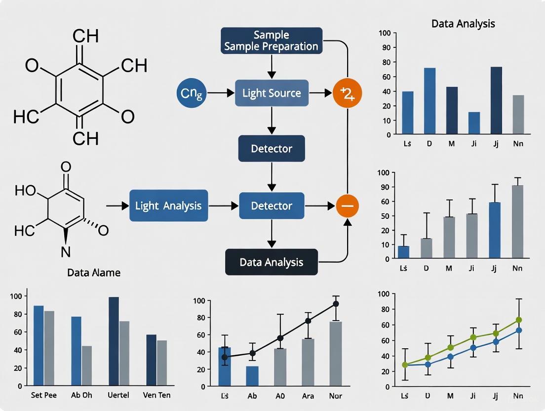
This resource provides practical guidance for researchers implementing path length amplification techniques to enhance sensitivity in absorption spectroscopy. The following guides and protocols are designed to help you troubleshoot common issues and effectively apply these methods in fields from analytical chemistry to pharmaceutical development.
Frequently Asked Questions (FAQs)
Q1: What is the fundamental principle behind using a scattering cavity to enhance sensitivity?
The core principle is based on the Beer-Lambert law (I = I₀ exp(-ε c l)), which states that measured absorbance is proportional to the optical path length (l) [5]. A scattering cavity significantly increases the effective path length that light travels through the sample. Light is trapped and undergoes multiple scattering events within the cavity, interacting with the sample numerous times before exiting, thereby amplifying the detected signal [5].
Q2: How does the sensitivity enhancement of a scattering cavity compare to that of an integrating sphere?
Both methods enhance sensitivity by increasing the effective path length, but their practical implementation differs. The published scattering cavity design demonstrated an average enhancement factor of over 10 times for model compounds like malachite green and crystal violet [5]. The exact enhancement factor for an integrating sphere can vary based on its design and reflectance properties [34]. The key advantage of the scattering cavity is its potential for simpler integration with standard cuvettes and spectrometers with minimal modification [5].
Q3: My sample is turbid and scatters light. Can I still use these amplification methods reliably?
Yes, in fact, these methods can be particularly advantageous for turbid samples. A key benefit of using an integrating sphere detector is its ability to help separate the contributions of molecular absorption from scattering. Specialized measurement models have been developed to interpret data from turbid samples like microalgae suspensions, allowing researchers to deconvolve the absorption and scattering signals [34].
Q4: What are the critical material properties for constructing an effective scattering cavity?
The cavity material should have:
- Very high diffuse reflectance (>80% in your wavelength range of interest) to efficiently trap light [5].
- Minimal intrinsic absorption (low absorption coefficient) to prevent signal loss from the cavity itself [5].
- Excellent machinability to form a cavity with the required geometry, such as an offset between entrance and exit holes to prevent direct light passage [5]. Hexagonal Boron Nitride (h-BN) is one material that meets these criteria well [5].
Troubleshooting Guides
Issue 1: Low or No Signal Enhancement
| Possible Cause | Diagnostic Steps | Solution |
|---|---|---|
| Incorrect cavity/sample geometry | Verify that the cavity exit port is offset from the entrance to prevent direct, non-scattered light from escaping [5]. | Reposition the sample cuvette or modify the cavity design to ensure multiple scattering events occur within the sample. |
| Poor cavity wall reflectance | Characterize the reflectance of your cavity material using a spectrophotometer, ideally across your measurement wavelength range [5]. | Switch to a high-diffuse-reflectance material like h-BN or a specialized Spectralon-like polymer. |
| Sample concentration too high | Check if your absorbance values (with amplification) are outside the ideal dynamic range of your detector (typically 0.5 - 2.5 Au) [35]. | Dilute the sample. The Beer-Lambert law's linearity, and thus the validity of the enhancement factor, holds best at low concentrations [5]. |
Issue 2: High Signal Noise or Unstable Baseline
| Possible Cause | Diagnostic Steps | Solution |
|---|---|---|
| Fluctuation in light source | Measure the baseline stability (I₀) with the cavity but without the sample over an extended period. | Allow the lamp to warm up sufficiently and use a power-regulated source. |
| Insufficient averaging | Observe if the noise decreases when you increase the number of spectral scans averaged by your spectrometer. | Increase the integration time or the number of averaged scans in your spectrometer software. |
| Stray light leaks | Conduct the experiment in a darkroom or carefully cover the setup to block ambient light. | Ensure the scattering cavity and all light paths are fully enclosed and light-tight. |
Detailed Experimental Protocol: Scattering Cavity Setup
This protocol details the method for achieving a >10x sensitivity boost using a scattering cavity, as demonstrated in Scientific Reports [5].
Materials and Equipment
Research Reagent Solutions & Essential Materials
| Item | Function/Brief Explanation |
|---|---|
| Halogen Lamp Light Source | Provides a broad-spectrum, stable incident light beam (I₀). |
| Spectrometer | Measures the intensity of light after it has passed through the system (I). |
| Boron Nitride (h-BN) Cavity | The scattering cavity itself. Its high diffuse reflectance and minimal absorption trap light effectively [5]. |
| Standard Cuvette | Holds the liquid sample. The cavity is designed to enclose this standard lab item [5]. |
| Linear Polarizers (2x) | Act as beam power attenuators (optional, for fine-tuning intensity) [5]. |
| Short-Pass Filter | Filters out wavelengths beyond the spectrometer's range to reduce noise (optional) [5]. |
Step-by-Step Procedure
- Cavity Fabrication: Machine the scattering cavity from a block of high-purity h-BN. The critical design feature is an offset of 10 mm between the entrance and exit holes. This ensures incident light strikes the cavity wall and undergoes multiple scattering, rather than passing directly through [5].
- System Assembly: Align the optical components in the following order: Halogen Lamp → (Optional) Linear Polarizers → (Optional) Short-Pass Filter → Scattering Cavity (with cuvette and sample inside) → Spectrometer.
- Reference Measurement (I₀): Place a cuvette filled with a blank solvent (e.g., deionized water) inside the scattering cavity. Collect a reference spectrum (I₀).
- Sample Measurement (I): Replace the blank with your sample solution (e.g., malachite green) at the desired concentration. Collect the sample spectrum (I) using the exact same configuration.
- Data Analysis: Calculate the absorbance as A = -log(I / I₀). Compare this value to the absorbance measured using a conventional, single-pass method with the same sample to determine your enhancement factor.
Expected Outcomes and Validation
- Quantitative Enhancement: For a well-aligned system with a low-concentration sample, you should observe an enhancement in absorbance of more than 10 times compared to the conventional method [5].
- Lower Limit of Detection (LOD): The method should significantly lower the LOD. The original study could detect malachite green concentrations as low as 0.004 µM using the scattering cavity, whereas the conventional method's LOD was 0.040 µM for the same compound [5].
Experimental Workflow and Concepts
Scattering Cavity Enhanced Absorbance Workflow
Pathlength Fundamentals in Spectroscopy
This technical support center provides troubleshooting and methodological guidance for researchers working with quantum dot (QD)-based photodetectors optimized for the infrared (IR) fingerprint region (approximately 500 cm⁻¹ to 1500 cm⁻¹) [36]. The following FAQs and guides are designed to help you overcome common experimental challenges and implement advanced techniques to enhance sensitivity in your absorption spectroscopy research.
Troubleshooting FAQs
Q1: My quantum dot solution has formed aggregates. What should I do?
- Recommendation: Centrifuge the vial at 2,000 x g for 1 minute. Pipette only the supernatant and avoid the pellet. This typically results in a loss of less than 10% of the product [37].
- Important Note: Once QD nanocrystals undergo significant aggregation, they cannot be re-dispersed. Freezing the product will also cause irreversible aggregation. If aggregation is severe, you will need to purchase a new product [37].
Q2: I am observing nonspecific background staining in my immunolabeling experiments with QD streptavidin conjugates. How can I reduce this?
- Use Recommended Buffer: Always use the Qdot Incubation Buffer, which is formulated to improve signal-to-background ratios. Other buffers can increase background variability [37].
- Block Endogenous Biotin: Tissues like spleen and kidney may contain endogenous biotin. Use an avidin/biotin blocking kit to prevent nonspecific signal [37].
- Optimize Antibody Concentration: Overly high concentrations of biotinylated secondary antibody can lead to nonspecific binding. Titrate both your secondary antibody and QD streptavidin conjugate to find the concentration that provides optimal specific signal with minimal background [37].
Q3: The photodetector signal from my QD device is weak or inconsistent. What are some potential causes?
- Check Filter Sets: Ensure you are using an appropriate filter set for the specific QD conjugate you are using. Consult the product manual for optimal filter specifications [37].
- Verify QD Fluorescence: Confirm that your QD conjugate is fluorescing by testing it with a hand-held ultraviolet lamp (long wave) or by performing a spot test on a microscope slide [37].
- Inspect for Precipitates: If using organic ITK QDs, a white precipitate may sometimes form. Remove it by spinning the solution at ~3,000 rpm for 3-5 minutes and use the supernatant immediately [37].
Q4: My FT-IR spectra are noisy or show strange negative peaks. How can I fix this?
- Eliminate Vibrations: FT-IR spectrometers are highly sensitive to physical disturbances. Ensure your instrument is placed on a stable surface away from pumps or other sources of vibration [38].
- Clean ATR Crystals: A contaminated crystal is a common cause of negative peaks. Clean the crystal thoroughly and perform a fresh background scan [38].
- Check Sample Homogeneity: For solid materials like plastics, the surface chemistry may differ from the bulk. Compare spectra from the surface and a freshly cut interior to check for surface oxidation or additives [38].
Experimental Protocols
Protocol 1: Optimizing QD Absorption Coefficient via the Nelder-Mead Algorithm
This methodology details the computational optimization of QD structures for maximum IR absorption at specific wavelengths [36].
1. Define Objective Function and Parameters The goal is to maximize the optical absorption coefficient at target wavenumbers (e.g., 600 cm⁻¹ and 800 cm⁻¹). The design parameters are the physical dimensions of the QD and its basic cell [36].
- For a semi-spherical QD: The radius (R).
- For a conical QD: The radius (R) and height (H).
- For a truncated conical QD: The top radius (R₁), bottom radius (R₂), and height (H).
- The basic cell containing the QD is defined by its radius (rb) and height (hb).
2. Model the Quantum System
- Hamiltonian Setup: Construct the system's Hamiltonian using the effective mass approximation, considering the axial symmetry of the QD structures [36]:
Ĥ = U(r,z) - (ħ²/2) [ (1/r) ∂/∂r (r/m_r ∂/∂r) + (-n²/(r² m_r)) + ∂/∂z (1/m_z ∂/∂z) ]WhereU(r,z)is the potential profile,ħis the reduced Planck's constant,nis the quantum number, andm_randm_zare the radial and axial effective masses, respectively. - Calculate Bound States: Diagonalize the Hamiltonian matrix to obtain the bound state energies (Ei, Ef) and their corresponding wavefunctions (ψi, ψf).
3. Calculate Absorption Transition Rate
- Apply Fermi's golden rule under the dipole approximation to compute the transition rate between initial and final states [36]:
R_fi = (π E₀²) / (2ħ) * |d_fi ⋅ ê| * δ(E_f - E_i - ħω) - The dipole moment
d_fiis calculated as:d_fi = q * ∫∫∫ ψ_f* r ψ_i r dr dφ dz
4. Implement the Optimization Algorithm
- Use the Nelder-Mead simplex algorithm to iteratively adjust the design parameters (R, H, etc.) with the objective of maximizing the absorption coefficient.
- Run the optimization within a defined set of physical constraints that reflect fabrication limitations.
5. Perform Sensitivity Analysis
- Conduct a 5% variation (tolerance) analysis on each optimized cell parameter to evaluate the robustness of the design and understand the effect of manufacturing imperfections on performance [36].
Protocol 2: Gap-Controlled Infrared Absorption Spectroscopy for Interface Analysis
This experimental protocol describes a low-cost method to isolate and analyze molecular interfaces, enhancing sensitivity to surface phenomena [20] [39].
1. Setup ATR-IR Spectroscopy
- Use a conventional Attenuated Total Reflection Infrared (ATR-IR) spectrometer. The sample is brought into contact with an IR-transparent crystal (e.g., diamond, ZnSe) to generate an evanescent wave that probes the sample surface.
2. Introduce Precise Gap Control
- Incorporate a distance-control mechanism (e.g., a piezoelectric stage) to precisely manipulate the nanometer-scale gap between the ATR crystal and the sample surface. This gap is varied systematically during data collection [20] [39].
3. Data Collection
- Collect a series of IR absorption spectra at different, precisely controlled gap distances.
4. Data Analysis with Multivariate Curve Resolution (MCR)
- Apply MCR analysis to the collected spectral series. This algorithm mathematically decomposes the data to extract the pure spectral components and their concentration profiles, effectively separating the weak interfacial signals from the dominant bulk background [20] [39].
Data Tables
Table 1: QD Structure Optimization Parameters and Results
This table summarizes key parameters and outcomes from the optimization of different InAs/GaAs QD shapes for IR absorption in the fingerprint region [36].
| QD Structure | Design Parameters | Objective Function | Key Optimization Finding |
|---|---|---|---|
| Semi-Spherical | Radius (R) | Maximize absorption at 600 cm⁻¹ & 800 cm⁻¹ | Considerable enhancement achieved at target wavelengths [36] |
| Conical | Radius (R), Height (H) | Maximize absorption at 600 cm⁻¹ & 800 cm⁻¹ | Considerable enhancement achieved at target wavelengths [36] |
| Truncated Conical | Top Radius (R₁), Bottom Radius (R₂), Height (H) | Maximize absorption at 600 cm⁻¹ & 800 cm⁻¹ | Considerable enhancement achieved at target wavelengths [36] |
| General Note | Basic cell size (radius rb, height hb) is also a key parameter. A 5% sensitivity analysis is recommended post-optimization [36]. |
Table 2: Essential Research Reagent Solutions
This table lists key materials used in the fabrication and analysis of quantum dot-based IR photodetectors.
| Item | Function / Description | Example & Notes |
|---|---|---|
| InAs/GaAs QDs | Active material for IR photodetection. Bandgap is tunable via size and shape control for fingerprint region targeting [36]. | Common self-assembled QD material; model is generic and can be applied to other III-V compounds [36]. |
| PbS CQDs | Colloidal QDs for SWIR photodetection and photovoltaics; offer size-tunable bandgap and solution processability [40] [41]. | High-performance dots; excitonic peak at 1350 nm or 1550 nm; can be ligand-exchanged for device fabrication [41]. |
| Ligand Exchange Chemicals | Replaces long, insulating ligands on synthesized QDs with shorter linkers to improve charge transport in thin films [40] [41]. | e.g., Benzenedithiol (BDT), Ethanedithiol (EDT) [41]. |
| QD Incubation Buffer | Specialized buffer for immunolabeling to improve specific signal and reduce background staining with QD conjugates [37]. | Qdot Incubation Buffer; alternative buffers may increase variability [37]. |
| Avidin/Biotin Blocking Kit | Blocks endogenous biotin in certain tissues to minimize nonspecific background signal in staining experiments [37]. | Essential for tissues like spleen and kidney [37]. |
Experimental Workflows
Diagram 1: QD Optimization Workflow
Diagram 1: Computational workflow for optimizing quantum dot absorption coefficient.
Diagram 2: Interface Spectroscopy Setup
Diagram 2: Gap-controlled ATR-IR workflow for interfacial molecular analysis.
Technical Support Center
Troubleshooting Guides
Guide 1: Addressing Poor Signal-to-Noise Ratio (SNR) in Live-Cell Measurements
A low SNR is a common challenge that can obscure vital data. The table below outlines symptoms, potential causes, and recommended solutions.
| Symptom | Possible Cause | Solution |
|---|---|---|
| Weak or noisy nitrile probe signal | Limited dynamic range due to strong water absorption [42] | Implement Solvent Absorption Compensation (SAC) to distinguish the analyte signal over the full dynamic range at each wavelength [42]. |
| Inconsistent readings between replicates | Coherence artifacts (speckles, fringes) from the laser source [43] | Use instrumentation with integrated hardware coherence reduction (e.g., ILIM) [43]. |
| High detector noise | Use of an unsuitable detector for the application | For QCL systems, utilize room-temperature microbolometer arrays designed for high spectral power density [43]. |
| Low signal from drug-protein complex | Analyte concentration is near or below the system's detection limit | Employ a double-beam QCL spectrometer with balanced detection; this can lower the detection limit for a test nitrile compound from 80 µM to 16 µM [44] [45]. |
Experimental Protocol: Solvent Absorption Compensation (SAC) This protocol enhances SNR by compensating for the strong IR absorption of water, which typically limits the dynamic range [42].
- Setup: Integrate an adaptive optical unit, such as an acousto-optic modulator or a rotating polarizer, into the QCL spectrometer beam path. This unit must adjust transmission efficiency rapidly as the laser wavelength scans [42].
- Calibration: Perform a reference scan with the aqueous solvent (e.g., buffer or culture medium) to characterize the strong water absorption profile.
- Measurement: For the protein solution sample, the SAC unit actively compensates for the solvent's absorption, freeing up the detector's dynamic range to capture the analyte's signal with high fidelity [42].
- Validation: This method has been shown to improve the signal-to-noise ratio by over 100 times and can extend the usable spectral range to up to 900 cm⁻¹ for proteins in aqueous solution [42].
Guide 2: Diagnosing and Correcting for Atypical Spectral Data
Unexpected spectral results can indicate issues with the instrumentation, sample, or experimental conditions.
| Symptom | Possible Cause | Solution |
|---|---|---|
| Absence of expected spectral shift upon drug addition | Failure of covalent drug binding or loss of protein viability in live cells. | Verify cell health and protein expression levels. Confirm drug activity using a complementary assay. |
| Large, unexpected baseline drift | Instability in the laser output power or alignment [46]. | Allow the laser to warm up and stabilize; check for premature laser failure by monitoring operational characteristics [46]. |
| Broad, distorted absorption peaks | Saturation of the detector due to excessive signal or coherence artifacts [43]. | Ensure the SAC unit is functioning correctly and adjust laser power. Activate coherence reduction hardware [43]. |
| Non-reproducible nitrile peak shifts | Changes in the local hydrogen-bonding environment not specific to drug binding [44]. | Run controlled experiments and use molecular dynamics simulations (e.g., with AMOEBA force field) to model and interpret shifts [44]. |
Experimental Protocol: Live-Cell Binding Assay Using Nitrile Probes This protocol details the methodology for detecting drug-protein interactions directly in live E. coli cells, using nitrile-incorporated Photoactive Yellow Protein (PYP) as a model system [44].
- Cell Preparation: Engineer E. coli cells to express the target protein (e.g., PYP) with a nitrile-containing amino acid (e.g., cyanoglutamine) at the specific binding site. Culture the cells to the desired density [44].
- Spectrometer Configuration: Use a double-beam QCL-based mid-IR transmission spectrometer. The double-beam design with balanced detection is critical for enhancing sensitivity and suppressing common-mode noise [44] [45].
- Data Acquisition: Place the live cell sample in an appropriate IR-transparent sample holder. Acquire mid-IR spectra over the relevant spectral range (e.g., the nitrile stretching region) before and after the addition of the drug molecule (e.g., para-coumaric acid for PYP) [44].
- Data Analysis: Identify the frequency of the nitrile absorption peak. A successful drug-binding event is indicated by a large spectral shift (e.g., up to 15 cm⁻¹), which reports on the change in the electrostatic environment around the nitrile probe [44].
Frequently Asked Questions (FAQs)
Q1: What are the key advantages of using a QCL spectrometer over FT-IR for live-cell studies? QCL spectrometers offer two major advantages for live-cell work: superior speed and enhanced sensitivity. The high spectral power density of QCLs allows for much faster data acquisition, enabling real-time monitoring of dynamic processes [43]. Furthermore, the laser's properties, when combined with techniques like double-beam detection and SAC, provide a much better signal-to-noise ratio, which is crucial for detecting weak signals from low-concentration analytes within the complex environment of a cell [44] [42].
Q2: Our lab is considering a QCL system. What are the main practical limitations we should be aware of? The primary limitation is the restricted spectral range compared to FT-IR. While FT-IR can access the entire mid-IR fingerprint region, a single QCL's tuning range is limited by its heterostructure design, though "bound-to-continuum" designs help broaden this [43]. Other considerations include:
- Laser Safety: High-power IR lasers require Class 1 laser enclosures with safety interlocks [43].
- Coherence Artifacts: Laser speckle and fringing can occur and must be mitigated with specialized hardware [43].
- Potential Device Failure: As with any complex laser, premature failure can occur, though machine learning models are being developed to predict this [46].
Q3: How does the Solvent Absorption Compensation (SAC) technique actually work? SAC is an active optical technique. As the Q laser scans through wavelengths, a component like an acousto-optic modulator dynamically adjusts the intensity of the light entering the sample. This pre-emptively "compensates" for the known strong absorption of the solvent (like water), preventing the detector from being overwhelmed. This ensures that the detector's full dynamic range is available to measure the much weaker absorption signals from the analyte, drastically improving the SNR [42].
Q4: Why are nitrile groups used as vibrational probes in these studies? Nitrile groups are excellent vibrational reporters because their absorption frequency in the mid-IR region is highly sensitive to the local electrostatic environment, such as changes in hydrogen bonding. When a drug binds to a protein, it can alter the environment around a strategically placed nitrile, causing a measurable shift in its IR absorption peak. This provides direct, label-free information about the binding event and the nature of the binding pocket [44].
The Scientist's Toolkit: Essential Research Reagents & Materials
The table below lists key materials and their functions for setting up QCL-based live-cell binding assays.
| Item | Function in the Experiment |
|---|---|
| Quantum Cascade Laser (QCL) | The tuned IR source with high spectral power density, enabling fast and sensitive measurements in the mid-IR range [43]. |
| Genetically Encoded Nitrile Probe | A site-specifically incorporated nitrile-containing amino acid (e.g., in PYP) that serves as a sensitive vibrational reporter of local environmental changes during drug binding [44]. |
| Double-Beam Spectrometer with Balanced Detection | An optical setup that minimizes common-mode noise, leading to a five-fold increase in sensitivity and a significantly improved signal-to-noise ratio [44] [45]. |
| Solvent Absorption Compensation (SAC) Unit | An adaptive optical component (e.g., acousto-optic modulator) that compensates for strong solvent absorption, freeing up dynamic range and improving SNR by >100x [42]. |
| Room-Temperature Microbolometer Array | A detector suitable for QCL-based widefield microscopy that does not require cryogenic cooling, allowing for high-speed chemical imaging [43]. |
Performance & Sensitivity Data
The following table summarizes key quantitative improvements offered by advanced QCL spectrometer configurations.
| Metric | Conventional FT-IR / Method | Advanced QCL-Based Method | Enhancement Factor / Key Detail |
|---|---|---|---|
| Detection Limit (Nitrile Probe) | ~80 µM [45] | ~16 µM [45] | 5-fold improvement (in live cells) [45] |
| Signal-to-Noise Ratio (SNR) | Limited by water absorption [42] | >100x improvement [42] | Enabled by Solvent Absorption Compensation (SAC) [42] |
| Nitrile Spectral Shift on Binding | — | Up to 15 cm⁻¹ [44] | Reports on changes in hydrogen-bonding environment [44] |
| Usable Spectral Range in Water | ~100 cm⁻¹ [42] | ~900 cm⁻¹ [42] | SAC enables broad spectral acquisition [42] |
Experimental Workflow and Technical Diagrams
Diagram 1: Live-cell drug-binding assay workflow.
Diagram 2: Double-beam QCL spectrometer with SAC.
Technical Support Center
Troubleshooting Guides & FAQs
FAQ: General Method Development
Q: How can I enhance the sensitivity of my UV-Vis method for detecting these drugs in biological fluids with low concentrations?
- A: To enhance sensitivity, employ pre-column derivatization. This technique involves chemically modifying the drug molecule to introduce a chromophore with a higher molar absorptivity (ε). For instance, Febuxostat can be derivatized with specific diazotizing reagents to form a highly absorbing azo dye complex, significantly lowering your limit of detection (LOD) in plasma samples.
Q: My calibration curves for tablet analysis are non-linear. What could be the cause?
- A: Non-linearity often arises from instrumental or chemical sources. First, ensure your spectrophotometer is calibrated for wavelength and absorbance accuracy. Chemically, it can be due to the association of drug molecules at high concentrations, deviations from the Beer-Lambert law, or interference from tablet excipients. Dilute your samples to a concentration range where the Beer-Lambert law is strictly followed and verify the absence of excipient interference by running a placebo sample.
FAQ: Sample Preparation
Q: What is the most efficient way to extract Febuxostat from plasma with high recovery?
- A: Protein Precipitation (PPT) followed by Liquid-Liquid Extraction (LLE) is highly effective. Precipitate proteins with acetonitrile (1:2 ratio, plasma:ACN), vortex, and centrifuge. Then, extract the supernatant with dichloromethane at an acidic pH (e.g., pH 3.0-4.0 with phosphate buffer). This two-step process removes proteins and lipids, yielding a clean extract with high recovery (>95%).
Q: I am getting low recovery for Finasteride during solid-phase extraction (SPE). What should I check?
- A: Low recovery in SPE for Finasteride is often due to improper sorbent conditioning or incomplete elution. Ensure the C18 sorbent is fully conditioned with methanol followed by water or a weak aqueous buffer. After sample loading, use a wash solvent with just enough strength to remove impurities without eluting the drug (e.g., 20% methanol in water). For elution, use a strong, pure organic solvent like acetonitrile or ethyl acetate and ensure you use a sufficient volume (e.g., 2 x 1 mL).
FAQ: Instrumentation & Analysis
Q: My baseline is noisy during HPLC-UV analysis of Methimazole. How can I stabilize it?
- A: Noisy baselines are commonly caused by mobile phase issues, air bubbles, or a contaminated flow cell. Degas your mobile phase thoroughly (e.g., by sonication under vacuum). Ensure your HPLC system is properly purged to remove air. If the problem persists, flush the system and the detector flow cell with a strong solvent (e.g., isopropanol) to remove any potential contaminants.
Q: The retention time for my analyte is drifting. What is the primary troubleshooting step?
- A: Retention time drift indicates an unstable chromatographic condition. The most common cause is an improperly controlled or fluctuating mobile phase pH. Prepare a fresh mobile phase buffer with precise pH adjustment and ensure the column temperature is maintained constant using the column heater.
Experimental Protocols
Protocol 1: Quantification of Febuxostat in Tablets by UV-Vis Spectrophotometry
- Standard Solution: Accurately weigh 10 mg of Febuxostat reference standard and dissolve in methanol in a 100 mL volumetric flask to make a 100 µg/mL stock solution.
- Sample Solution: Weigh and powder 20 tablets. Transfer a powder equivalent to 10 mg of Febuxostat to a 100 mL volumetric flask, add about 70 mL of methanol, sonicate for 20 minutes, dilute to volume with methanol, and filter.
- Derivatization: Pipette 1 mL of the standard or sample solution into a 10 mL volumetric flask. Add 1 mL of 0.1% w/v sodium nitrite solution and 1 mL of 1M HCl. Let it stand for 5 minutes. Add 1 mL of 0.5% w/v ammonium sulfamate, followed by 1 mL of 0.1% w/v N-(1-Naphthyl)ethylenediamine dihydrochloride (NEDD). Dilute to volume with methanol and measure the absorbance at 540 nm after 10 minutes.
- Calculation: Construct a calibration curve (e.g., 2-20 µg/mL) from the standard solution and calculate the drug content in the tablet sample.
Protocol 2: HPLC-UV Analysis of Finasteride in Human Plasma
- Chromatographic Conditions:
- Column: C18 (250 mm x 4.6 mm, 5 µm)
- Mobile Phase: Acetonitrile:Water (55:45, v/v)
- Flow Rate: 1.0 mL/min
- Detection: UV at 210 nm
- Column Temperature: 30°C
- Sample Preparation (LLE):
- To 1 mL of plasma sample in a centrifuge tube, add 50 µL of internal standard solution (e.g., Testosterone propionate, 10 µg/mL).
- Add 200 µL of 0.1M sodium hydroxide and vortex mix.
- Add 3 mL of diethyl ether, vortex for 3 minutes, and centrifuge at 4000 rpm for 10 minutes.
- Transfer the organic layer to a clean tube and evaporate to dryness under a gentle stream of nitrogen.
- Reconstitute the residue with 200 µL of mobile phase and inject 20 µL into the HPLC system.
Data Presentation
Table 1: Summary of Validated UV-Vis Methods for Tablet Analysis
| Drug | λmax (nm) | Linearity Range (µg/mL) | Regression Equation | LOD (µg/mL) | LOQ (µg/mL) | % Recovery (Mean ± RSD) |
|---|---|---|---|---|---|---|
| Febuxostat | 540* | 2 - 20 | y = 0.045x + 0.002 | 0.15 | 0.45 | 99.8 ± 1.2 |
| Methimazole | 252 | 1 - 12 | y = 0.068x - 0.005 | 0.08 | 0.25 | 100.2 ± 0.8 |
| Finasteride | 210 | 5 - 50 | y = 0.021x + 0.011 | 0.30 | 0.90 | 99.5 ± 1.5 |
*After derivatization with NEDD.
Table 2: Summary of HPLC Methods for Biological Fluid Analysis
| Drug | Matrix | Sample Prep | Linearity Range (ng/mL) | LOD (ng/mL) | LOQ (ng/mL) | % Recovery |
|---|---|---|---|---|---|---|
| Febuxostat | Human Plasma | LLE (DCM) | 10 - 2000 | 3.0 | 10.0 | 96.5% |
| Methimazole | Rat Serum | PPT (ACN) | 50 - 5000 | 15.0 | 50.0 | 98.2% |
| Finasteride | Human Plasma | LLE (Diethyl Ether) | 1 - 100 | 0.3 | 1.0 | 95.8% |
The Scientist's Toolkit
| Research Reagent / Material | Function |
|---|---|
| C18 Solid-Phase Extraction (SPE) Cartridges | For selective extraction and purification of analytes from complex biological matrices like plasma. |
| N-(1-Naphthyl)ethylenediamine dihydrochloride (NEDD) | Derivatizing agent used to form a colored, highly absorbing azo complex with Febuxostat for enhanced UV-Vis detection. |
| Dichloromethane (DCM) / Diethyl Ether | Organic solvents for Liquid-Liquid Extraction (LLE), effectively partitioning drugs from aqueous biological samples. |
| Acetonitrile (HPLC Grade) | Primary organic component of the mobile phase in reversed-phase HPLC; also used for protein precipitation. |
| Phosphate Buffer (pH ~3.5 & ~7.4) | Adjusts and controls the pH of samples and mobile phases to optimize extraction efficiency, retention, and peak shape. |
| Internal Standard (e.g., Testosterone propionate) | A compound added in a constant amount to correct for variability in sample preparation and instrument injection. |
Visualizations
UV-Vis Tablet Analysis Workflow
Biological Sample Prep Workflow
Sensitivity Enhancement Pathways
Optimizing Performance and Mitigating Analytical Errors
Troubleshooting Guide: FAQs on Critical Parameters
FAQ 1: Why do I observe poor measurement repeatability in my absorption spectroscopy experiments, and what is the most likely cause?
Poor short-term repeatability is most frequently caused by a mismatch in analyte concentration between your sample and the reference or working standard. This mismatch creates a scale-offset effect. For example, in high-precision measurements of CO₂, a mismatch of just 1 µmol/mol can induce an offset of several ppm in the triple oxygen isotope (∆'¹⁷O) results [47].
- Recommended Action: Implement rigorous procedures to ensure the analyte concentration is identical between sample and reference. For data already affected, apply empirical corrections based on the measured concentration difference to improve reproducibility [47].
FAQ 2: My instrument shows significant long-term drift, even in a controlled lab environment. What parameters should I investigate first?
The dominant factors affecting long-term stability are drifts in optical cell temperature and pressure [47]. Unrecognized instrumental drift from these parameters can be misinterpreted as genuine sample variations, such as seasonal trends in air monitoring studies [47].
- Recommended Action: Continuously monitor and log optical cell temperature and pressure alongside your spectral data. Implement active control systems to stabilize these parameters. For critical applications, use built-in temperature and pressure sensors to apply real-time corrections to the spectral data [47].
FAQ 3: How does reactor or cell design impact the sensitivity and accuracy of my measurements?
Sub-optimal reactor design can introduce significant errors by altering the microenvironment at the catalyst surface. Many operando reactors are batch-operated with planar electrodes, which can lead to poor mass transport of reactants, buildup of pH gradients, and changes in local electrolyte composition. These effects can convolute intrinsic reaction kinetics with mass transport effects, leading to misleading mechanistic conclusions [48].
- Recommended Action: Where possible, design or select reactors that minimize the path length between the reaction event and the spectroscopic probe. For example, depositing a catalyst directly onto a pervaporation membrane in a DEMS cell can drastically improve response time and signal for reactive intermediates [48].
FAQ 4: What are the best practices for ensuring my real-time spectroscopic measurements are sterile and non-invasive?
The measurement technique must be inherently suitable for sterile operation. In-line monitoring with a non-invasive optical probe inserted directly into the bioreactor is the preferred method for maintaining sterility. The probe design must allow for steam-in-place or other sterilization procedures. Alternatively, on-line monitoring using a sterile flow cell or bypass loop can be used, ensuring the sample is recirculated without contamination [49].
- Recommended Action: Select optical probes and flow cells designed for sterile bioprocess applications. Validate that the entire flow path can withstand standard sterilization protocols without degradation [49].
Quantitative Data: Sensitivity of Key Parameters
The following table summarizes the quantitative impact of key parameters on measurement sensitivity, as identified in the research.
Table 1: Sensitivity of Spectroscopic Measurements to Critical Parameters
| Parameter | Impact on Measurement | Quantitative Effect | Technique / Context |
|---|---|---|---|
| Analyte Concentration Mismatch | Short-term repeatability (scale-offset) | Several ppm per 1 µmol/mol mismatch [47] | TILDAS (∆'¹⁷O in CO₂) [47] |
| Optical Cell Temperature | Long-term stability & drift | A primary factor for instrumental drift [47] | TILDAS (∆'¹⁷O in CO₂) [47] |
| Optical Cell Pressure | Long-term stability & drift | A primary factor for instrumental drift [47] | TILDAS (∆'¹⁷O in CO₂) [47] |
| Fiber Sensor Temperature | Direct physical measurement | -3.38 nm/°C (enhanced sensitivity) [50] | Fiber Fabry-Perot Interferometer [50] |
| Fiber Sensor Pressure | Direct physical measurement | 20.91 nm/MPa (enhanced sensitivity) [50] | Fiber Fabry-Perot Interferometer [50] |
Experimental Protocols
Protocol for Verifying and Correcting Concentration Mismatch Effects
This protocol is designed to diagnose and correct for errors induced by mismatches in CO₂ concentration, as derived from high-precision TILDAS instrumentation [47].
- Instrument Setup: Operate the Tunable Infrared Laser Direct Absorption Spectroscopy (TILDAS) instrument in high-precision dual-inlet mode.
- Systematic Variation: Prepare a series of samples where the CO₂ concentration is intentionally varied while the isotopic composition is kept constant.
- Data Collection: For each concentration level, record the measured value of the target analyte (e.g., ∆'¹⁷O).
- Calibration Curve: Plot the measured ∆'¹⁷O value against the CO₂ concentration difference (sample - reference). The slope of this plot quantifies the scale-offset sensitivity (in ppm per µmol/mol).
- Application of Correction: For future experimental measurements, measure the precise CO₂ concentration of both sample and reference. Use the predetermined sensitivity factor to apply an empirical correction to the raw ∆'¹⁷O data, thereby negating the offset effect [47].
Protocol for In-line Bioprocess Monitoring Using Vibrational Spectroscopy
This protocol outlines the steps for real-time, non-invasive monitoring of a fermentation process, ensuring sterility and accurate data acquisition [49].
- Probe Sterilization: Before inoculation, insert the vibrational spectroscopy probe (e.g., Raman or mid-IR) into the bioreactor through a standard port. Follow standard bioprocess protocols to sterilize the entire system, including the probe housing.
- Baseline Collection: Once the process is stabilized at the initial setpoints (temperature, pH, dissolved oxygen), collect a background spectrum of the sterile medium.
- Real-time Data Acquisition: Initiate the fermentation. Configure the spectrometer to automatically collect and average multiple spectra at regular intervals (e.g., every 5 minutes) to reduce high-frequency noise.
- Data Pre-processing: In real-time, subject the raw spectra to pre-processing algorithms. This typically includes smoothing, baseline correction, and normalization.
- Chemometric Analysis: Use a pre-calibrated multivariate model (e.g., Partial Least Squares regression) to convert the pre-processed spectra into quantitative values for critical process variables (e.g., biomass, substrate, or product concentration) [49].
- Process Control: Feed these real-time predictions into the process control system to enable automated adjustments for optimal productivity.
Parameter Optimization Workflow
The following diagram illustrates the logical workflow for diagnosing and optimizing key parameters to enhance measurement sensitivity and stability.
The Scientist's Toolkit: Research Reagent Solutions
Table 2: Essential Materials and Technologies for Enhanced Sensing
| Item / Technology | Function | Application Context |
|---|---|---|
| Fabry-Perot Interferometer (FPI) | A high-finesse optical cavity used to create an interference pattern. Shifts in this pattern, caused by changes in the cavity's physical length or refractive index, are used for ultra-sensitive measurement. | Used as the core sensing element in fiber-optic sensors for temperature and pressure [50]. |
| Vernier Effect | An optical technique where two interferometers with similar free spectral ranges are combined. It magnifies the shift of the interference envelope, dramatically enhancing sensitivity to external parameters. | Used in conjunction with FPIs to achieve temperature sensitivity of -3.38 nm/°C and pressure sensitivity of 20.91 nm/MPa [50]. |
| Chemical Ionization Mass Spectrometer (CIMS) | Ionizes trace gas analytes via chemical reactions with a reagent ion, minimizing fragmentation. Provides highly sensitive detection for a wide range of compounds. | Detection of trace gases in atmospheric science; sensitivity is normalized to reagent ion concentration for cross-instrument comparison [51]. |
| Tunable Infrared Laser Direct Absorption Spectroscopy (TILDAS) | Uses a narrow-linewidth, wavelength-tunable laser to measure the specific absorption features of a gas-phase molecule. Enables high-specificity and high-sensitivity quantification of target analytes and their isotopologues. | High-precision measurements of ∆'¹⁷O in CO₂ for paleoenvironmental and atmospheric sciences [47]. |
| Metamaterials (LSPR) | Artificially structured materials that support localized surface plasmon resonance (LSPR). They confine light to subwavelength scales, generating strong electromagnetic fields that drastically enhance the interaction with analytes. | Platform for surface-enhanced spectroscopy techniques like SEIRA and SERS, lowering detection limits for molecular fingerprinting [52]. |
Troubleshooting Guide & FAQs
This section addresses common challenges researchers face when applying the Nelder-Mead Simplex algorithm to optimize quantum dot (QD) structures for enhanced infrared (IR) photodetection.
FAQ 1: My optimization process converges slowly or gets stuck. What parameters should I check? Slow convergence often relates to the initial simplex setup or algorithm parameters. The Nelder-Mead is a direct search method, so ensure your initial guesses for the QD design parameters are physically realistic. The optimization study for InAs/GaAs QDs used a specific objective function targeting maximization of the optical absorption coefficient at wavenumbers of 600 and 800 cm⁻¹ [53]. If the algorithm stalls, consider adjusting the termination tolerance criteria or implementing a restart strategy with a new initial simplex.
FAQ 2: How do I validate that my optimized absorption coefficient results are physically sound and not an artifact of the algorithm? After optimization, perform a sensitivity analysis. The InAs/GaAs QD study conducted a 5% sensitivity analysis for each QD cell parameter to evaluate the effects of tolerances around the optimized design [53]. This step is crucial for assessing the robustness of your solution and ensuring it's viable for fabrication, where minor parameter variations are inevitable.
FAQ 3: The algorithm optimizes for specific wavelengths, but the performance drops elsewhere. Is this expected? Yes, this is a characteristic of targeted optimization. The referenced study specifically maximized absorption at 600 and 800 cm⁻¹ for the "fingerprint" IR region [53]. The objective function was designed for these wavelengths. If your application requires broad-spectrum performance, you must reformulate the objective function to maximize the integral of the absorption coefficient across your desired wavelength range.
FAQ 4: Can this optimization approach be applied to different QD materials or shapes? The study confirms that the presented Nelder-Mead optimization approach is generic [53]. It can be adapted to different wavelengths, various QD structures (comparing semi-spherical, conical, and truncated conical dots were mentioned), and different QD and barrier materials by adjusting the underlying physical model in the objective function.
Experimental Protocol & Workflow
This section details the methodology for maximizing the absorption coefficient of quantum dot structures using the Nelder-Mead Simplex algorithm, based on the published protocol [53].
The following table outlines the key stages of the optimization workflow:
| Stage | Key Action | Primary Output |
|---|---|---|
| 1. Physical Modeling | Calculate the bound-to-bound absorption coefficient based on bounded states estimation using the effective mass Hamiltonian diagonalization. | Theoretical absorption spectrum for a given initial QD structure. |
| 2. Objective Definition | Define the objective function for the optimizer, e.g., maximizing absorption at specific wavenumbers (600 and 800 cm⁻¹). | A scalar function representing the performance metric to be maximized. |
| 3. Algorithm Execution | Run the Nelder-Mead simplex algorithm, iteratively reflecting, expanding, and contracting the simplex based on objective function evaluation. | An optimized set of QD design parameters (e.g., size, composition). |
| 4. Validation & Analysis | Perform a 5% sensitivity analysis on each optimized QD cell parameter to study tolerance effects. | A robust, fabrication-tolerant QD design with a maximized absorption coefficient. |
Detailed Workflow Diagram
The diagram below visualizes the logical workflow and iterative process of the Nelder-Mead optimization.
Research Reagent & Computational Solutions
The following table lists the essential computational and material components used in this field of research.
| Item Name | Type/Function | Specific Role in Experiment |
|---|---|---|
| InAs/GaAs Quantum Dots | Material System | Self-assembled QDs serve as the active medium for IR photodetection, whose absorption coefficient is being optimized [53]. |
| Effective Mass Hamiltonian Model | Computational Model | Used to calculate the electronic bounded states and the initial bound-to-bound absorption coefficient before optimization [53]. |
| Nelder-Mead Simplex Algorithm | Optimization Algorithm | A gradient-free direct search method used to find the QD parameters that maximize the optical absorption coefficient at target wavelengths [53]. |
| Sensitivity Analysis Framework | Validation Method | Assesses the robustness of the optimized QD design by evaluating performance with a ±5% variation in cell parameters, informing fabrication tolerances [53]. |
Integration with Sensitivity Enhancement in Spectroscopy
The optimization of QD absorption coefficients directly contributes to the broader thesis goal of enhancing sensitivity in absorption spectroscopy. Superior photodetectors, enabled by optimized QDs, allow for the detection of weaker signals, thereby lowering the limit of detection for spectroscopic instruments [53].
Other parallel research strategies for sensitivity enhancement include:
- Path Length Extension: Using a boron nitride (h-BN) scattering cavity to trap light, increasing the effective optical path length by more than ten times and significantly boosting absorbance signals [5].
- Signal Processing Techniques: Applying stochastic resonance methods in Quartz-Enhanced Photoacoustic Spectroscopy (QEPAS) to amplify trace gas detection signals [54].
- Solvent Compensation: Employing Solvent Absorption Compensation (SAC) in mid-IR spectroscopy to neutralize the strong absorption of water, improving the signal-to-noise ratio for protein solutions by over 100 times [42].
The relationship between these techniques is illustrated below, showing how algorithmic material design fits into the broader spectrum of sensitivity enhancement.
This technical support center provides troubleshooting and methodological guidance for researchers fabricating Surface-Enhanced Infrared Absorption (SEIRA) active substrates, a critical technology for enhancing sensitivity in absorption spectroscopy research [31].
Frequently Asked Questions (FAQs)
Q1: What are the most common problems affecting the performance of a SEIRA substrate? Poor performance often stems from uneven nanostructure formation, which leads to inconsistent signal enhancement across the chip surface. This can be caused by improper reaction conditions, contaminated starting materials, or non-uniform metal deposition [55] [56].
Q2: How can I make the SEIRA substrate fabrication process more cost-effective? Research indicates that using porous, three-dimensional structures like copper foam as a support material can significantly reduce costs. Silver nanoparticles can be deposited onto the foam through a simple chemical replacement reaction, avoiding the need for expensive vacuum systems or complex nanolithography [56].
Q3: My SEIRA substrate shows weak enhancement. What should I check? First, verify the key fabrication parameters:
- Reaction Time: Ensure the metal deposition reaction is not too short (leading to insufficient nanoparticle growth) or too long (causing over-aggregation).
- Precursor Concentration: Confirm the concentrations of metal salts and reducing agents.
- Substrate Uniformity: Use microscopy (e.g., SEM) to check that metal nanoparticles are evenly distributed across the support structure [56].
Q4: How can I validate the reproducibility and stability of my fabricated chips? Perform repeated SEIRA measurements on different spots of the same chip and across different chips from the same fabrication batch. A good substrate will show a low variation in the intensity of characteristic absorption peaks (e.g., less than 5% relative standard deviation). Stability can be checked by measuring the SEIRA signal from a standard analyte over time [56].
Troubleshooting Guide
The following table outlines common experimental issues, their potential causes, and recommended solutions.
| Problem Observed | Possible Causes | Recommended Solutions |
|---|---|---|
| Uneven Enhancement | Non-uniform metal deposition; Inconsistent pore structure in support foam [55] [56]. | Ensure vigorous and consistent stirring during the reduction reaction; Use support materials with a uniform, consistent pore size [56]. |
| Weak SEIRA Signal | Incomplete nanoparticle formation; Insufficient density of "hot spots" [31] [56]. | Optimize reaction time and precursor concentration; Validate nanoparticle growth with SEM/EDX characterization [56]. |
| Poor Reproducibility | Slight variations in reaction temperature, timing, or chemical batch quality [56]. | Standardize all protocols; Use precise, calibrated equipment; Prepare fresh reducing agent solutions for each batch. |
| High Background Noise | Contamination on the substrate surface or in the chemical solutions [55]. | Implement rigorous cleaning of the support foam before fabrication; Use high-purity reagents and solvents. |
Detailed Experimental Protocol: Ag-Supported Copper Foam SEIRA Chip
This protocol details the synthesis of an economical and flexible SEIRA-active chip based on a published methodology [56].
Materials and Reagents
- Support Material: Copper foam (e.g., ~1 cm x 1 cm pieces)
- Metal Precursor: Silver nitrate (AgNO₃) solution
- Reducing Agent: Hydroxylamine hydrochloride (NH₂OH·HCl) solution
- Solvents: Deionized water, ethanol
- Safety Equipment: Lab coat, gloves, and safety glasses.
Step-by-Step Fabrication Procedure
- Pretreatment: Clean the copper foam pieces sequentially with diluted hydrochloric acid, ethanol, and deionized water in an ultrasonic bath to remove surface oxides and contaminants. Dry in a nitrogen stream.
- Preparation of Solutions: Prepare fresh aqueous solutions of AgNO₃ (e.g., 50 mM) and NH₂OH·HCl (e.g., 100 mM).
- Reduction and Deposition: Immerse the clean copper foam into the AgNO₃ solution under constant stirring. The copper will act as a reducing agent, initiating a replacement reaction where silver ions are reduced to form nanoparticles on the foam surface.
- Enhancement (Optional): To further control growth and coverage, a separate reduction step using NH₂OH·HCl can be employed.
- Rinsing and Drying: Thoroughly rinse the fabricated chip with deionized water and ethanol to remove any residual ions or loosely attached particles. Dry the final ACF-based SEIRA-active chip under a nitrogen atmosphere.
Validation and Performance Assessment
- Characterization: Use Scanning Electron Microscopy (SEM) and Energy-Dispersive X-ray Spectroscopy (EDX) to confirm the uniform distribution of silver nanoparticles on the copper foam [56].
- SEIRA Testing: Apply a known standard analyte (e.g., febuxostat or methimazole) to the chip and acquire its infrared spectrum. A successful chip will show significant enhancement (e.g., 15-22 times) of the analyte's characteristic IR peaks compared to its conventional IR spectrum [56].
The Scientist's Toolkit: Research Reagent Solutions
Essential materials and their functions for the ACF-based SEIRA chip fabrication.
| Item | Function in the Experiment |
|---|---|
| Copper Foam | A three-dimensional, porous scaffold that provides a high surface area for nanoparticle deposition and acts as a reducing agent. |
| Silver Nitrate (AgNO₃) | The precursor source for silver (Ag⁺) ions, which are reduced to form plasmonically active silver nanoparticles. |
| Hydrochloric Acid (HCl) | Used in the initial cleaning step to remove native oxide layers from the copper foam surface. |
| Hydroxylamine Hydrochloride (NH₂OH·HCl) | A reducing agent used to assist in the controlled reduction of silver ions, ensuring robust nanoparticle formation [56]. |
SEIRA Chip Fabrication and Testing Workflow
The following diagram illustrates the logical sequence of steps involved in creating and validating a SEIRA-active chip.
Frequently Asked Questions (FAQs)
Q1: What are the most common types of interferences in absorption spectroscopy? The two primary categories are spectral interferences and matrix effects.
- Spectral Interferences occur when an absorption line or band from a non-analyte component overlaps with the signal from your target analyte. This can be caused by other atoms with very close absorption lines, broad molecular absorption bands, or light scattering from particulates in the sample [57] [58].
- Matrix Effects refer to the combined influence of all other components in the sample on the measurement of the analyte. In techniques like LC-MS, this often manifests as ion suppression or enhancement in the ion source when other compounds co-elute with the analyte [59] [60].
Q2: How can I experimentally detect and assess matrix effects in my LC-MS method? You can use these common techniques [60]:
- Post-Column Infusion: A qualitative method where an analyte is infused into the LC eluent post-column while a blank matrix extract is injected. Signal dips or enhancements in the chromatogram indicate regions of ion suppression or enhancement.
- Post-Extraction Spike: A quantitative method where the signal response of an analyte in a pure solution is compared to the response of the same analyte spiked into a blank matrix extract. The difference indicates the extent of the matrix effect.
Q3: My samples have very low analyte concentrations. What strategies can enhance sensitivity despite a complex matrix?
- Increase Optical Path Length: Using a scattering cavity made of a highly reflective, low-absorbing material (e.g., hexagonal boron nitride) can significantly increase the effective path length of light through the sample, enhancing sensitivity by more than tenfold without complex alignment [5].
- Exploit Overlapping Lines: In some cases, using a set of overlapping absorption lines can increase the total absorption signal, thereby lowering the detection limit. This requires sophisticated correction methods, like second harmonic spectral reconstruction (2f-SR), to deconvolve the individual contributions [61].
Q4: Are there instrumental techniques to automatically correct for background spectral interference? Yes, atomic absorption spectrometers often come with built-in background correction systems. The two most common are [57]:
- Deuterium Lamp Correction: Uses a continuum source to measure broadband background absorption, which is then subtracted from the total absorption measured by the line source (e.g., a hollow cathode lamp).
- Zeeman Effect Correction: Applies a magnetic field to the atomizer to split the analyte's absorption line. Measurements taken with and without the magnetic field allow for precise subtraction of background signals.
Troubleshooting Guides
Guide 1: Managing Spectral Overlap in Atomic and Molecular Spectroscopy
Problem: The absorption signal from your analyte is overlapped by a spectral feature from an interferent, leading to inaccurate concentration measurements.
Solutions:
- Instrumental Background Correction: Utilize the spectrometer's built-in correction system, such as a Deuterium (D₂) lamp or the Zeeman effect, to automatically measure and subtract broadband background absorption [57].
- Chemical Separation or Modification: Modify the sample preparation or introduction system to remove the interfering species or prevent its formation. For example, using a higher-temperature flame can prevent the formation of refractory oxides that cause molecular absorption [57].
- Advanced Signal Processing: For complex overlapping absorption lines, employ mathematical techniques to separate the signals.
- Second Harmonic Spectral Reconstruction (2f-SR): This method involves restoring the second harmonic (2f) signal based on laser characteristics and then performing a fast multi-peak fitting to separate the interference from overlapping absorption lines, significantly improving measurement accuracy [61].
- Direct Absorption Fitting (DAF): This fits the direct absorption spectrum using algorithms like continuous wavelet transform combined with chaos particle swarm optimization to separate overlapping lines [61].
Guide 2: Mitigating Matrix Effects in Quantitative LC-MS Analysis
Problem: The presence of the sample matrix causes suppression or enhancement of the analyte's ionization, compromising the accuracy, reproducibility, and sensitivity of the quantitation.
Solutions:
- Improve Sample Cleanup: Optimize the sample preparation protocol (e.g., using Solid-Phase Extraction - SPE) to remove more of the interfering matrix components before analysis [60] [62].
- Chromatographic Optimization: Adjust chromatographic conditions (mobile phase, column type, gradient) to shift the analyte's retention time away from the region where matrix interferences elute [59] [60].
- Calibration Strategies to Compensate for ME:
- Stable Isotope-Labeled Internal Standard (SIL-IS): This is the gold standard. The labeled standard has nearly identical chemical properties and chromatographic retention to the analyte, so it experiences the same matrix effects, allowing for perfect compensation [59] [60].
- Standard Addition Method: Add known amounts of the analyte to the sample itself. This method accounts for the matrix effect without requiring a blank matrix and is useful for endogenous compounds [59].
- Matrix-Matched Calibration: Prepare calibration standards in a blank matrix that is similar to the sample. This can be challenging if a truly blank matrix is not available [60].
Experimental Protocols for Enhanced Sensitivity and Interference Correction
Protocol 1: Sensitivity Enhancement Using a Scattering Cavity
This protocol details a method to significantly increase optical path length and sensitivity in absorption spectroscopy using a scattering cavity [5].
Principle: A sample is enclosed in a cavity made of a material that causes multiple light scattering. This traps light, forcing it to pass through the sample numerous times before exiting, dramatically increasing the effective path length.
Materials and Reagents:
- Scattering Cavity: Machined from hexagonal Boron Nitride (h-BN), which has high diffuse reflectance (>80% above 500 nm) and low absorption [5].
- Cuvette: Standard commercial cuvette to hold the sample solution.
- Light Source: Halogen lamp or other broadband source.
- Spectrometer: Standard unit (e.g., Ocean Optics HR4000).
Procedure:
- Place the cuvette containing the sample solution inside the h-BN scattering cavity.
- The cavity should have offset entrance and exit holes to prevent light from passing directly through the sample.
- Direct light from the source into the cavity entrance.
- Collect the light that exits through the offset hole using the spectrometer.
- For reference (I₀), measure the intensity using deionized water in the cuvette.
Expected Outcomes: This setup demonstrated an average enhancement factor of over 10 in absorbance for malachite green and crystal violet solutions, allowing for detection at sub-micromolar concentrations [5].
Protocol 2: Correcting Overlapping Absorption Lines with 2f-SR
This protocol is for correcting interference from overlapping absorption lines in gas-phase spectroscopy using Second harmonic Spectral Reconstruction (2f-SR) [61].
Principle: The method corrects for errors caused by gas temperature and laser characteristics, then reconstructs the 2f signal to accurately separate overlapping lines.
Procedure:
- Measure Gas Temperature: Use the temperature characteristics of two selected absorption lines. Calculate the temperature based on the ratio of their second harmonic (2f) peak values, using a pre-established relationship (e.g., T = -3·R₂f + 116.61) [61].
- Recover the 2f Signal: Account for the influence of laser parameters (linear and nonlinear modulation coefficients K₁, K₂ and phase shifts φ₁, φ₂) on the measured 2f signal waveform. This step eliminates distortion caused by the laser itself [61].
- Perform Fast Multi-Peak Fitting: Using the recovered 2f signal and known line positions, perform a fitting algorithm to deconvolve and separate the individual contributions of the overlapping absorption lines.
Expected Outcomes: Application of this method for CH₄ measurement using overlapping lines resulted in a measurement accuracy better than 0.8% and reduced the minimum detection limit by two to three orders of magnitude [61].
The Scientist's Toolkit: Key Research Reagent Solutions
The following table lists essential materials and their functions for managing interferences, as derived from the cited research.
| Item | Function/Application | Key Reference |
|---|---|---|
| Hexagonal Boron Nitride (h-BN) | Material for building scattering cavities; provides high diffuse reflectance with minimal absorption to enhance effective optical path length. | [5] |
| Stable Isotope-Labeled Internal Standards (SIL-IS) | Internal standard for LC-MS; compensates for matrix effects by exhibiting nearly identical behavior to the analyte during sample preparation and ionization. | [59] [60] |
| Deuterium (D₂) Lamp | A continuum light source used in atomic absorption spectrometers for background correction of broad-band molecular absorption and light scattering. | [57] |
| Hydrogen/Helium Gas | Reaction gases in a Collision Reaction Interface (CRI) for ICP-MS; selectively react with or dissociate polyatomic interfering ions (e.g., Ar₂⁺). | [63] |
| Solid-Phase Extraction (SPE) Cartridges | Sample preparation tool for LC-MS; selectively purifies and pre-concentrates the analyte, removing many matrix components that cause ion suppression/enhancement. | [60] [62] |
The table below consolidates key quantitative findings from the research reviewed in this guide.
| Technique | Key Performance Metric | Result | Citation |
|---|---|---|---|
| Scattering Cavity | Sensitivity Enhancement Factor | >10x increase in absorbance | [5] |
| 2f-SR for CH₄ measurement | Measurement Accuracy | Better than 0.8% | [61] |
| 2f-SR for CH₄ measurement | Minimum Detection Limit (MDL) Reduction | Reduced by 2-3 orders of magnitude | [61] |
| CRI with H₂ for Se detection | Removal of Ar₂⁺ Interference | Complete removal at ~120 mL/min H₂ flow | [63] |
Workflow and System Diagrams
The following diagrams illustrate the logical workflow and setup of key techniques discussed in this guide.
2f-SR Overlap Correction Workflow
Scattering Cavity Setup
FAQs: Core Concepts of Robustness Testing
1. What is the difference between robustness and ruggedness in analytical methods? Robustness and ruggedness measure different aspects of method reliability. Robustness is "a measure of [an analytical procedure's] capacity to remain unaffected by small but deliberate variations in method parameters" listed in the procedure, such as mobile phase pH, flow rate, or column temperature [64] [65]. Ruggedness, often addressed as intermediate precision, refers to "the degree of reproducibility of test results obtained by the analysis of the same samples under a variety of normal test conditions," such as different laboratories, analysts, or instruments [65]. In short, robustness deals with internal method parameters, while ruggedness deals with external conditions [65].
2. When should I perform a robustness test during method development? It is recommended to perform robustness testing during the method development and optimization phase, prior to formal validation [64] [65]. Investigating robustness early allows you to identify critical parameters that could affect your method and define system suitability test (SST) limits based on the results. This proactive approach saves time and resources by preventing future failures during method transfer or validation [64] [65].
3. Which experimental design should I choose for a robustness test? The choice of design depends on the number of factors you need to investigate.
- Plackett-Burman Designs: Highly efficient for screening a large number of factors (e.g., 7-11) where only main effects are of interest. The number of experiments is a multiple of four [64] [66] [65].
- Full Factorial Designs: Examine all possible combinations of factors. Suitable for a smaller number of factors (typically <5), as the number of runs (2^k for k factors) grows exponentially [65].
- Fractional Factorial Designs: A subset of full factorial designs used for a larger number of factors. They are more efficient but involve confounding (aliasing) of some interaction effects with main effects [65].
4. A factor I'm testing has a non-linear effect on the response. What should I do? If you suspect a factor has a non-linear effect (e.g., absorbance vs. detection wavelength where the nominal level is at the maximum), using a symmetric interval around the nominal level might hide the effect. In such cases, an asymmetric interval is more informative. You might choose one extreme level and use the nominal level as the other point of comparison to properly capture the response behavior [64].
Troubleshooting Guide: Common Robustness Testing Issues
| Problem | Possible Cause | Solution |
|---|---|---|
| Uncontrolled Drift in Responses | Time-dependent effects, such as HPLC column aging or instrument performance drift, confounding factor effects [64]. | Execute experiments in an anti-drift sequence or introduce replicated nominal experiments at regular intervals to model and correct for the time effect [64]. |
| High Variability in SST Responses | Critical method parameters (e.g., mobile phase pH, column temperature) are not robust; their small variations cause significant changes in responses like resolution [64]. | Use the robustness test results to define tighter acceptance criteria for System Suitability Tests (SST). If necessary, refine the method by optimizing the sensitive factors [64]. |
| Inconsistent Method Transfer | The robustness of the method was not fully understood, and the receiving laboratory operates with normal variations in equipment or reagents that were not tested [67]. | Invest effort in a comprehensive robustness study during development. Use advanced instrument capabilities to fine-tune parameters (e.g., gradient delay volume) during transfer to match original performance [67]. |
| Ambiguous or Confounded Factor Effects | Using a screening design with low resolution where main effects are aliased with two-factor interactions [65]. | Select a higher-resolution design (e.g., Resolution V or higher) where possible. Use prior knowledge to avoid aliasing important factors. Consider adding more experiments to de-alias the confounded effects [65]. |
Experimental Protocols for Key Robustness Tests
Protocol 1: Robustness Test for an HPLC Assay Using a Plackett-Burman Design
This protocol outlines a systematic approach to evaluating the robustness of an HPLC method for quantifying an active compound and related impurities [64].
1. Selection of Factors and Levels
- Select 7-8 method parameters likely to affect the results. For HPLC, these typically include:
- Mobile phase pH (±0.1-0.2 units)
- Column temperature (±2°C)
- Flow rate (±0.05 mL/min)
- Detection wavelength (±2 nm)
- Percentage of organic solvent in mobile phase (±1-2%)
- Different columns (same type, different batches)
- Buffer concentration (±5%)
- Define a nominal (normal) level, a low extreme level (-1), and a high extreme level (+1) for each quantitative factor. The interval should represent variations expected during method transfer. For qualitative factors (e.g., column), define two discrete levels [64].
2. Experimental Design and Execution
- Select a 12-run Plackett-Burman design to evaluate the 8 factors. This design also allows for the estimation of 3 dummy factor effects for statistical comparison [64].
- Run the experiments in a randomized order to minimize bias from uncontrolled variables. If drift is suspected, use an anti-drift sequence or include replicate nominal experiments for correction [64].
- For each run, prepare and inject a blank, a reference standard solution, and a sample solution representative of the actual sample matrix [64].
3. Data Analysis and Interpretation
- Calculate Factor Effects: For each response (e.g., % recovery, critical resolution), calculate the effect of each factor (E_x) using the formula:
E_x = (Average response at high level) - (Average response at low level)[64]. - Statistical Significance: Compare the absolute value of each factor effect to a critical effect value. This can be derived from the effects of dummy factors or using a statistical algorithm like Dong's algorithm [64].
- Draw Conclusions: Factors with effects smaller than the critical effect are considered non-significant, indicating the method is robust to variations in that parameter. Significant effects identify parameters that require control through strict system suitability criteria [64].
Protocol 2: Enhancing Sensitivity in Absorption Spectroscopy Using a Scattering Cavity
This protocol describes a method to significantly boost the sensitivity of conventional absorption spectroscopy by increasing the effective optical path length, directly supporting research into sensitivity enhancement techniques [5].
1. Principle The sensitivity of absorption spectroscopy is proportional to the optical path length (OPL) according to the Beer-Lambert law. By enclosing a sample within a highly reflective, scattering cavity made of a material like hexagonal Boron Nitride (h-BN), light is trapped and undergoes multiple scattering events, dramatically increasing the effective OPL and thus the measured absorbance [5].
2. Materials and Setup
- Light Source: Halogen lamp or a supercontinuum laser (e.g., FYLA Iceblink with >3W power and 450-2300 nm range for high intensity and broad coverage) [68].
- Scattering Cavity: Machined from h-BN (>99.5% purity), which provides high diffuse reflectance (>80% at >500 nm) and minimal absorption. The cavity design should have offset entrance and exit holes to prevent direct light passage [5].
- Detection: A spectrometer (e.g., Ocean Insight HR4000) [5].
- Sample: A standard cuvette placed inside the scattering cavity.
3. Experimental Procedure
- Baseline Measurement: Place a blank solvent (e.g., deionized water) in the cuvette inside the cavity. Measure the reference intensity spectrum (I₀).
- Sample Measurement: Replace the blank with the sample solution. Measure the intensity spectrum (I) under identical conditions.
- Data Processing: Calculate the absorbance as A = -log(I/I₀). Compare this absorbance to that obtained using a conventional single-pass method with the same sample. The enhancement factor is the ratio of the absorbance with the cavity to the absorbance without it [5].
The Scientist's Toolkit: Key Research Reagent Solutions
| Item | Function / Application |
|---|---|
| Plackett-Burman Experimental Design | A highly efficient screening design used to identify which of many method parameters have a significant effect on the results, making it ideal for robustness testing [66] [65]. |
| h-BN (hexagonal Boron Nitride) Scattering Cavity | Used to enhance sensitivity in absorption spectroscopy. Its high diffuse reflectance and minimal absorption trap light, increasing the effective pathlength through the sample by more than 10 times [5]. |
| Cavity Enhanced Absorption Spectrometer (CEASpec) | A fiber-based instrument that uses an optical cavity with highly reflective mirrors to circulate light multiple times through a tiny sample volume (picolitres), boosting sensitivity for analyzing small volumes or low concentrations [69]. |
| Advanced LC Systems with Automated Scouting | Liquid chromatography systems equipped with software and hardware to automatically screen multiple parameters (columns, pH, temperature), accelerating method development and robustness assessment [67]. |
| Supercontinuum Laser (e.g., Iceblink) | A high-power, broadband laser light source ideal for cavity-enhanced spectroscopy. Its high intensity and wide spectral range enable sensitive and accurate measurements across many wavelengths [68]. |
Workflow & Pathway Visualizations
Robustness Test Workflow
Cavity-Enhanced Sensitivity Pathway
Method Validation, Comparative Analysis, and Green Chemistry Metrics
FAQs: Core Validation Parameters
Q1: What is the practical difference between accuracy and precision in analytical results?
Accuracy refers to how close a measured value is to the true value, while precision describes the reproducibility or repeatability of measurements. In practice, a method can be precise (producing consistent results) without being accurate (if all results are biased from the true value). For regulatory compliance, both are essential. In a recent HPLC method validation for pharmaceutical analysis, accuracy was demonstrated with recovery values between 98.2%–101.5%, while precision was confirmed by relative standard deviation (RSD) values below 2% for both intra-day and inter-day measurements [70].
Q2: How is the linear range determined and validated during method development?
The linear range is established by analyzing a series of standard solutions at different concentrations and evaluating the relationship between response and concentration. The correlation coefficient (R²) is calculated, with values >0.999 typically considered excellent. For example, in the simultaneous HPLC analysis of metoclopramide and camylofin, linearity was validated over ranges of 0.375–2.7 μg/mL and 0.625–4.5 μg/mL, respectively, with R² values exceeding 0.999 [70].
Q3: What specific factors are tested to prove method robustness?
Robustness is verified by deliberately introducing small, controlled variations in method parameters and observing their impact on performance. Key parameters typically include:
- Flow rate variations (e.g., 0.9–1.1 mL/min)
- Column temperature fluctuations (e.g., 35–45°C)
- Mobile phase composition changes
- pH variations in buffer solutions The method is considered robust if these variations do not significantly affect critical performance metrics such as resolution, symmetry, or quantification accuracy [70].
Q4: How can sensitivity be enhanced in absorption spectroscopy techniques?
Beyond fundamental instrument optimization, advanced signal processing techniques can significantly improve sensitivity. For instance, in Quartz-Enhanced Photoacoustic Spectroscopy (QEPAS), a stochastic resonance (SR) algorithm has been employed to amplify weak signals by leveraging noise rather than suppressing it. This approach enhanced the output signal by a factor of 3 and reduced the minimum detection limit for methane from 329 ppb to 85 ppb [71].
Troubleshooting Guides
Table 1: Common Analytical Issues and Solutions
| Problem Symptom | Potential Causes | Recommended Solutions | Related Validation Parameter |
|---|---|---|---|
| Poor precision and high variation between replicates | Insufficient instrument stabilization, sample degradation, inconsistent injection technique | Ensure proper instrument warm-up, check sample stability, verify injection consistency, increase equilibration time | Precision |
| Consistent bias in results across runs | Incorrect standard preparation, calibration error, matrix effects | Verify standard purity and preparation steps, check calibration curve, implement standard addition method | Accuracy |
| Non-linear response at higher or lower concentrations | Detector saturation, insufficient detector response, outside linear dynamic range | Dilute samples, verify detector wavelength, establish appropriate concentration range | Linearity and Range |
| Method performance changes between instruments or operators | Inadequate method robustness, overly sensitive to small parameter variations | Test method under varied conditions (flow rate, temperature, pH), document allowable tolerances | Robustness |
| Inadequate signal-to-noise ratio for trace analysis | Insufficient detection capability, high background noise, suboptimal conditions | Implement signal enhancement techniques, optimize instrument parameters, use appropriate sample pre-concentration | Sensitivity (LOD/LOQ) |
Troubleshooting Sensitivity Issues in Spectroscopic Techniques:
For absorption spectroscopy methods, if you encounter insufficient sensitivity:
Verify Fundamental Parameters: Ensure hollow cathode lamps are properly aligned and within their usable lifetime. Check that gas flows and burner head conditions are optimized for atomic absorption techniques [72] [73].
Consider Advanced Signal Processing: Implement algorithms like stochastic resonance (SR) that can enhance weak signals. The SR approach processes signals using a first-order nonlinear Langevin equation and can be solved numerically using the fourth-order Runge-Kutta method for optimal results [71].
Optimize Physical Components: In QEPAS systems, ensure proper alignment of acoustic micro-resonators and the quartz tuning fork. Use a preamplifier to enhance signals before demodulation by a lock-in amplifier [71].
Validate Enhancement Techniques: When implementing any sensitivity improvement strategy, re-validate method parameters including accuracy, precision, and linearity to ensure overall data quality remains acceptable.
Experimental Protocols
Protocol 1: HPLC Method Validation for Accuracy and Precision
This protocol outlines the procedure for validating accuracy and precision in HPLC methods, based on pharmaceutical analysis examples [70].
Materials and Equipment:
- HPLC system with UV detector
- Analytical balance (readability 0.1 mg)
- pH meter
- Appropriate chromatography column (e.g., phenyl-hexyl column)
- Mobile phase components (methanol, ammonium acetate, glacial acetic acid)
- Standard reference materials
Procedure:
- Mobile Phase Preparation: Prepare 20mM ammonium acetate buffer adjusted to pH 3.5 using glacial acetic acid. Mix with methanol in a 65:35 ratio (aqueous:organic). Filter through a 0.45μm nylon membrane and degas ultrasonically before use.
Standard Solution Preparation: Accurately weigh reference standards and prepare stock solutions. Dilute to appropriate concentrations for calibration curves (e.g., 0.375–2.7 μg/mL for metoclopramide and 0.625–4.5 μg/mL for camylofin).
Accuracy Testing (Recovery Study):
- Prepare placebo samples lacking the active analyte
- Spike with known concentrations of analyte at three levels (e.g., 80%, 100%, 120% of target)
- Analyze six replicates at each level
- Calculate recovery percentage: (Measured Concentration / Spiked Concentration) × 100%
- Acceptable recovery: 98-102%
Precision Testing:
- Repeatability: Analyze six replicates of the same concentration on the same day by the same analyst
- Intermediate Precision: Analyze the same samples on different days, by different analysts, or using different instruments
- Calculate Relative Standard Deviation (RSD) for both studies
- Acceptable precision: RSD < 2%
Data Analysis:
- Calculate mean, standard deviation, and RSD for all measurements
- Perform statistical analysis to compare results between different conditions
Protocol 2: Signal Enhancement Using Stochastic Resonance in QEPAS
This protocol details the implementation of a stochastic resonance algorithm to enhance sensitivity in absorption spectroscopy [71].
Materials and Equipment:
- QEPAS system with quartz tuning fork (QTF)
- Distributed feedback (DFB) laser source (e.g., 1651 nm for methane detection)
- Current driver and temperature controller for laser
- Function generator
- Preamplifier circuit
- Lock-in amplifier
- Data acquisition system
- Computer with appropriate signal processing software
Procedure:
- System Setup:
- Configure the DFB laser with appropriate current and temperature controls
- Position the QTF and acoustic micro-resonators in the optical path
- Set up modulation parameters: use wavelength modulation with second-harmonic detection
- Determine the resonance frequency (f₀) of the QTF via frequency sweeping
Signal Acquisition:
- Direct the collimated laser beam through the gas sample and QTF assembly
- Apply a sinusoidal modulation signal at f₀/2 to optimize photoacoustic signals
- Amplify the piezoelectric signal from the QTF using a three-stage preamplifier
- Demodulate the signal using a lock-in amplifier
- Acquire data using a DAQ system
Stochastic Resonance Processing:
- Implement the monostable SR system using the first-order nonlinear Langevin equation: where U(x) is the system potential function, s(t) is the photoacoustic signal, and Dξ(t) represents Gaussian white noise.
- Use the fourth-order Runge-Kutta method to solve the discrete stochastic differential equation
- Optimize potential function parameters (a and b) for maximum signal-to-noise ratio enhancement
Performance Validation:
- Compare output signals before and after SR processing
- Quantify enhancement by calculating the improvement in signal-to-noise ratio
- Verify that the minimum detection limit is reduced post-processing
- Ensure that signal distortion is minimized during the enhancement process
Signaling Pathways and Experimental Workflows
HPLC Method Validation Workflow
QEPAS Signal Enhancement Process
The Scientist's Toolkit: Research Reagent Solutions
Table 2: Essential Materials for Absorption Spectroscopy and Method Validation
| Item | Function | Application Example |
|---|---|---|
| Ammonium Acetate Buffer | Provides controlled pH mobile phase for HPLC separation | Maintaining pH 3.5 for separation of metoclopramide and camylofin [70] |
| Methanol (HPLC Grade) | Organic modifier in reversed-phase chromatography | Mobile phase component (35%) for drug analysis [70] |
| Reference Standards | Certified materials for calibration and accuracy assessment | Establishing calibration curves for quantitative analysis [70] |
| Quartz Tuning Fork (QTF) | Acoustic wave detection element in QEPAS | Transducing photoacoustic signals to electrical signals [71] |
| DFB Laser | Excitation source for spectroscopic detection | 1651 nm laser for methane detection in QEPAS [71] |
| Acoustic Micro-Resonators | Enhance acoustic signal intensity in QEPAS | Tubes positioned near QTF to amplify photoacoustic effect [71] |
| Hollow Cathode Lamps | Element-specific light source for atomic absorption | Required for each element determined by AAS [73] |
| Nylon Membrane Filters (0.45μm) | Remove particulate matter from mobile phases | Ensuring clean, bubble-free mobile phase for HPLC [70] |
Troubleshooting Guides
Guide 1: Resolving Low Sensitivity in Spectrophotometric Analysis
Problem: Absorbance readings are too low for reliable quantification of low-concentration analytes.
- Potential Cause: Short optical path length or low molar absorptivity of the analyte.
- Solution:
- Implement a scattering cavity to increase the effective optical path length. Research shows this can enhance sensitivity by more than tenfold [5].
- Use a cuvette with a longer path length.
- Confirm the selected wavelength matches the analyte's absorption maximum.
Problem: Overlapping absorption bands from multiple compounds.
- Potential Cause: Lack of separation in spectrophotometry leads to spectral interference.
- Solution:
- Employ chemometric analysis techniques like Multivariate Curve Resolution – Alternating Least Squares (MCR-ALS) to resolve overlapping signals [74].
- Consider switching to a chromatographic method if the sample mixture is too complex.
Guide 2: Addressing Peak Anomalies in UFLC-DAD Analysis
Problem: Shoulder peaks or suspected co-elution in chromatogram.
- Potential Cause: Inadequate chromatographic resolution; peaks that appear pure with a single-wavelength UV detector may reveal impurities with a DAD.
- Solution:
- Use the DAD's spectral data to check for peak purity. A pure peak will have identical spectra across its entire width [75].
- Optimize the mobile phase composition or gradient program to improve separation.
- Consider using a column with a smaller particle size for higher efficiency.
Problem: Discrepancies between UV and DAD results for the same sample.
- Potential Cause: Fundamental differences in detection capabilities. A UV detector captures data at a single, fixed wavelength, while a DAD scans the entire UV-Vis spectrum [75].
- Solution:
- Do not directly compare quantitative results from the two detectors without cross-validation.
- For method transfer, re-validate the method fully on the new instrument system.
Frequently Asked Questions (FAQs)
Q1: When should I choose spectrophotometry over UFLC-DAD for routine drug assay? Spectrophotometry is preferable when the application is cost-sensitive, the sample matrix is simple, the analyte has a strong chromophore, and high throughput is required. Research on metoprolol tartrate (MET) assays found UV spectrophotometry to be substantially more cost-effective and environmentally friendly for quality control of tablets, provided the concentration is within the method's limits [76].
Q2: Can I directly transfer a method from an HPLC-UV to an HPLC-DAD system? While often possible, a method should not be transferred without verification. The DAD provides superior spectral information that can reveal co-eluting impurities invisible to a single-wavelength UV detector. Method performance characteristics, including specificity, LOD, and LOQ, should be re-assessed during the transfer [75] [77].
Q3: How can I improve the sensitivity of my absorption spectroscopy method without changing instruments? Incorporating a scattering cavity is a highly effective strategy. A study using a hexagonal boron nitride (h-BN) cavity demonstrated a tenfold enhancement in measured absorbance for malachite green and crystal violet solutions by dramatically increasing the effective optical path length through multiple light scattering [5].
Q4: What are the key advantages of UFLC-DAD compared to conventional HPLC? UFLC (Ultra-Fast Liquid Chromatography) provides shorter analysis time, increased peak capacity, and lower consumption of samples and solvents. When coupled with a DAD, it also offers comprehensive spectral data for each peak, enabling peak purity assessment and identification of unresolved components [76] [78].
Q5: Why does my UFLC-DAD method have a longer run time than my spectrophotometric analysis? This is expected. Spectrophotometry often involves simple dilution and direct measurement, while UFLC-DAD includes a chromatographic separation step before detection. The trade-off is that UFLC-DAD provides superior specificity for complex mixtures, which is worth the additional time for many applications [76] [79].
Comparative Experimental Data
Table 1: Validation Parameters for Spectrophotometry vs. UFLC-DAD
Data for Metoprolol Tartrate (MET) Assay, adapted from [76]
| Validation Parameter | Spectrophotometry (UV) | UFLC-DAD |
|---|---|---|
| Linear Range | Concentration-dependent (limited at high concentrations) | Wide dynamic range |
| Specificity/Selectivity | Lower (susceptible to matrix interference) | High (chromatographic separation + spectral confirmation) |
| Sensitivity (LOD/LOQ) | Suitable for higher concentration APIs | Superior for trace analysis |
| Accuracy & Precision | High (% R.S.D. < 1.5) [79] | High (% R.S.D. < 1.5) [79] |
| Sample Consumption | Larger volumes often required | Minimal volume due to high sensitivity |
| Analysis Speed | Very fast (minutes per sample) | Fast, but longer than spectrophotometry (includes separation) |
| Solvent Consumption | Low (dilution only) | Low for UFLC, higher than spectrophotometry |
| Environmental Impact (AGREE score) | Superior Greenness | Good Greenness |
Table 2: Key Research Reagent Solutions
Essential materials for implementing the discussed techniques
| Reagent / Material | Function | Application Context |
|---|---|---|
| Hexagonal Boron Nitride (h-BN) Cavity | A scattering material with high diffuse reflectance and low absorption used to create a scattering cavity that dramatically increases effective path length. | Sensitivity enhancement in absorption spectroscopy [5]. |
| Malachite Green / Crystal Violet | Model analytes with high water solubility and known absorption maxima (617 nm and 590 nm, respectively). | Method validation and sensitivity testing in absorption spectroscopy [5]. |
| Zorbax SB-C18 Column | A reversed-phase HPLC column (4.6 x 250 mm, 5 µm) for compound separation. | Stationary phase for HPLC-DAD analysis of pharmaceuticals [78]. |
| Methanol & Acetonitrile (HPLC Grade) | Common organic modifiers used in the mobile phase for chromatographic elution. | Mobile phase component for HPLC/UFLC [78] [79]. |
| Potassium Dihydrogen Orthophosphate | Buffer salt to control the pH and ionic strength of the mobile phase. | Aqueous component of mobile phase for ionic strength and pH control [78]. |
Detailed Experimental Protocols
Protocol 1: Sensitivity Enhancement in Absorption Spectroscopy Using a Scattering Cavity
Based on [5]
Objective: To significantly lower the Limit of Detection (LOD) in absorption spectroscopy by increasing the effective optical path length.
Materials and Equipment:
- Standard UV-Vis spectrophotometer (e.g., Ocean Optics HR4000)
- Halogen lamp light source
- Custom-made scattering cavity (e.g., from hexagonal boron nitride, h-BN)
- Standard cuvette
- Sample solutions (e.g., malachite green or crystal violet in water)
Procedure:
- Setup: Place the scattering cavity around the standard cuvette. The cavity should have an entrance and an exit port for light, with the exit port offset from the entrance to prevent direct transmission of light.
- Blank Measurement: Fill the cuvette with the pure solvent (e.g., deionized water). Measure the reference intensity (I₀) with the cavity.
- Sample Measurement: Replace the solvent with the sample solution. Measure the intensity (I) with the cavity.
- Data Analysis: Calculate the absorbance as A = -log(I/I₀). Compare the absorbance value obtained with the cavity to that obtained using the conventional method (cuvette without cavity) for the same sample concentration. The ratio demonstrates the enhancement factor.
Protocol 2: Development and Validation of a UFLC-DAD Method for API Quantification
Objective: To develop a validated, rapid UFLC-DAD method for the quantification of an Active Pharmaceutical Ingredient (API) in a dosage form.
Materials and Equipment:
- UFLC system equipped with a DAD detector
- C18 reversed-phase column (e.g., with sub-2µm particles)
- API reference standard
- Pharmaceutical dosage form (e.g., tablets)
- HPLC-grade solvents and water
Procedure:
- Mobile Phase Optimization: Test different ratios of organic modifier (e.g., acetonitrile) and aqueous buffer to achieve a sharp, symmetric peak with a short retention time.
- Sample Preparation:
- Standard Solution: Accurately weigh and dissolve the API reference standard in an appropriate solvent.
- Tablet Solution: Weigh and powder tablets. Dissolve an accurately weighed portion of the powder equivalent to the API dose in solvent, sonicate, and filter.
- System Suitability: Inject the standard solution to ensure parameters like theoretical plates and tailing factor meet acceptance criteria.
- Method Validation:
- Linearity: Prepare and analyze a series of standard solutions at different concentrations (e.g., 5-50 µg/mL). The regression coefficient (r²) should be >0.999.
- Accuracy: Perform a recovery study by spiking a pre-analyzed sample with known amounts of standard.
- Precision: Check repeatability (multiple injections of the same solution) and intermediate precision (different days, analysts).
- Specificity: Confirm that the API peak is pure and free from interference from excipients or degradation products using the DAD's peak purity function.
- LOD/LOQ: Determine based on signal-to-noise ratios of 3:1 and 10:1, respectively.
Workflow and Technique Selection Diagrams
Technique Selection Workflow
Sensitivity Enhancement Principle
Troubleshooting Guide: Common ANOVA Issues in Method Comparison
1. My ANOVA results show a significant F-test, but I cannot find which specific groups differ. What should I do?
- Problem: A significant ANOVA F-test indicates that not all group means are equal but doesn't identify which specific pairs differ [80] [81].
- Solution: Perform post-hoc tests specifically designed for multiple comparisons [82]. Use:
- Tukey's HSD when comparing all possible pairs of groups, especially with unequal sample sizes [82].
- Bonferroni correction when testing only a predetermined set of comparisons [82].
- Avoid performing multiple t-tests without adjustment, as this causes alpha inflation and increases false positive findings [82].
2. My data violates the assumption of equal variances between groups. Can I still use ANOVA?
- Problem: Homogeneity of variance is a key ANOVA assumption [80] [81].
- Solution:
- Test the assumption: Use Levene's test or Bartlett's test to check for equal variances.
- Alternatives: If variances are unequal, consider:
- Data transformation (e.g., log transformation) to stabilize variances.
- Welch's ANOVA, which does not require the assumption of equal variances.
- Non-parametric tests such as the Kruskal-Wallis test if data is also non-normal.
3. How do I handle non-normal data distributions in my ANOVA model?
- Problem: ANOVA assumes normally distributed response variables within each group [81] [83].
- Solution:
- Check normality: Use Shapiro-Wilk test or Q-Q plots.
- Address violations:
- For large sample sizes, rely on the Central Limit Theorem which provides robustness against normality violations [83].
- Apply data transformations (e.g., square root, log).
- Use non-parametric alternatives like Kruskal-Wallis.
- Consider generalized linear models (GLMs) for specific non-normal distributions.
4. I have multiple factors influencing my recovery experiment. How do I account for them?
- Problem: Single-factor (one-way) ANOVA may be insufficient for complex experimental designs [83].
- Solution: Use higher-order ANOVA designs:
- Two-way ANOVA: For two categorical factors (e.g., treatment type and sample source) [80] [83]. This model can also test for interaction effects between factors.
- Three-way ANOVA: For three categorical factors, though interpretation becomes more complex [83].
- Include blocking variables: Use ANOVA with blocking to account for confounding variables (e.g., different experiment days, instrument operators) [81].
5. My experimental design has multiple measurements from the same subject. Which ANOVA should I use?
- Problem: Repeated measurements violate the assumption of independence [83].
- Solution: Use repeated measures ANOVA to properly account for within-subject correlations [83]. This model specifically handles data where the same experimental units are measured under different conditions or time points.
Frequently Asked Questions (FAQs)
Q1: When should I choose ANOVA over a t-test?
- Use a t-test when comparing means between exactly two groups [80] [81].
- Use ANOVA when comparing means across three or more groups, or when you have more than one categorical independent variable (factor) [80] [81] [83].
Q2: What is the difference between one-way and two-way ANOVA?
- One-way ANOVA has one categorical independent variable (factor) with three or more levels [80] [81].
- Two-way ANOVA has two categorical independent variables, allowing assessment of both main effects and interaction effects between the factors [80] [83].
Q3: How do I interpret the ANOVA table output?
- Focus on the F-statistic and p-value for each factor and interaction [81] [83].
- A p-value < 0.05 typically indicates a statistically significant effect [81] [84].
- The sum of squares (SS) shows how much variance is explained by each factor [81].
- Mean squares (MS) is calculated as SS divided by degrees of freedom [81].
Q4: What are fixed factors versus random factors in ANOVA?
- Fixed factors: All levels of interest are included in the experiment (e.g., specific treatment types) [83].
- Random factors: Only a random sample of levels are included from a larger population (e.g., multiple research sites) [83].
- The distinction affects how results are generalized and which F-tests are constructed.
Q5: How can ANOVA be applied in spectroscopic recovery studies?
- ANOVA can partition variance in spectroscopic data to identify significant experimental factors [85] [86].
- In FT-IR spectroscopic imaging, ANOVA helps quantify sources of variation (biological, technical, measurement noise) [85].
- Advanced ANOVA-based methods like ASCA, rMANOVA, and GASCA can handle complex multivariate spectroscopic data [86].
Experimental Protocol: ANOVA for Method Comparison in Recovery Studies
Purpose: To statistically compare the performance of multiple analytical methods or recovery protocols using ANOVA.
Step-by-Step Procedure:
Experimental Design
- Define the factor(s) of interest (e.g., extraction method, sample preparation technique).
- Determine the number of levels for each factor (e.g., Method A, B, C).
- Include appropriate replication (typically n ≥ 3) for each factor level combination.
- Randomize run order to avoid confounding time effects.
Data Collection
- Measure a continuous response variable relevant to recovery (e.g., percentage recovery, absorbance, concentration).
- Ensure measurements follow standard operating procedures.
- Record data in a structured format with columns for treatment groups and response values.
Assumption Checking
- Normality: Test using Shapiro-Wilk or examine Q-Q plots.
- Homogeneity of variances: Use Levene's test or Bartlett's test.
- Independence: Ensure experimental runs are independent through proper design.
ANOVA Execution
- Use statistical software (e.g., R, Prism, SPSS).
- For one-way ANOVA:
aov(response ~ factor, data = dataset)in R [81]. - For two-way ANOVA:
aov(response ~ factor1 * factor2, data = dataset). - Record F-statistics, degrees of freedom, and p-values from output.
Post-hoc Analysis (if ANOVA is significant)
- Perform appropriate multiple comparisons:
- Tukey's HSD: For all pairwise comparisons.
- Dunnett's test: When comparing all treatments to a control.
- Bonferroni: For a predetermined number of comparisons.
Results Interpretation
- Report significant main effects and interactions.
- Include descriptive statistics (means, standard deviations) for each group.
- Visualize results with bar charts (means ± SD) and indicate significant differences.
ANOVA Selection Guide
The following flowchart will help you select the appropriate type of ANOVA for your experimental design:
Research Reagent Solutions
| Item | Function in Recovery Studies |
|---|---|
| Standard Solutions | Used in recovery experiments to estimate proportional systematic error by adding known quantities of analyte to samples [87]. |
| Interferent Solutions | Contain potential interfering substances to test for constant systematic errors in analytical methods [87]. |
| Quality Control Materials | Patient specimens or pools used to test method performance under realistic conditions containing various substances found in real samples [87]. |
| Matrix-matched Materials | Samples with similar composition to actual specimens but without analyte of interest, used for preparing calibration standards [87]. |
| Internal Standards | Compounds added to samples to correct for variability in sample preparation and analysis. |
Variance Partitioning in Complex Experimental Designs
The following diagram illustrates how variance is partitioned in a complex ANOVA model with multiple factors, similar to designs used in spectroscopic imaging studies [85]:
Multiple Comparison Tests Guide
| Test | Best Use Case | Key Characteristics | Type I Error Control |
|---|---|---|---|
| Tukey's HSD | All pairwise comparisons with unequal group sizes [82]. | Conservative approach, protects family-wise error rate. | Strong control, minimizes false positives. |
| Newman-Keuls | Theory development research where small differences matter [82]. | More powerful than Tukey, tests means against grand mean. | Less conservative, higher power but more false positives. |
| Bonferroni | Predetermined number of comparisons [82]. | Simple adjustment: α/m where m is number of tests. | Strong control but can be overly conservative. |
| Scheffé | All possible contrasts (simple and complex) [82]. | Most flexible, tests any conceivable contrast. | Conservative, maintains α for all possible contrasts. |
| Dunnett | Multiple treatments vs. single control [82]. | Specialized for comparison to control group. | More powerful than Tukey for this specific case. |
The AGREE (Analytical GREEnness Metric Approach) is a comprehensive, open-source software tool designed to evaluate the environmental impact of analytical procedures. It translates the 12 principles of Green Analytical Chemistry (GAC) into a unified, easily interpretable score, providing a pictogram that clearly communicates a method's greenness[CITATION:8]. This tool is particularly significant for researchers in absorption spectroscopy, a field where methods often involve reagents, energy consumption, and waste generation. As the scientific community strives to make laboratories more sustainable, AGREE offers a standardized way to quantify and improve the environmental footprint of analytical techniques, including those focused on enhancing sensitivity, such as scattering cavity-enhanced absorption spectroscopy[CITATION:1] or quartz-enhanced photoacoustic spectroscopy[CITATION:5].
Troubleshooting Guides and FAQs
Frequently Asked Questions (FAQs)
Q1: What is the difference between AGREE and AGREEprep? AGREE is a metric that evaluates the greenness of overall analytical methods based on the 12 principles of green analytical chemistry[CITATION:8]. AGREEprep is a specific metric tailored for evaluating the environmental impact of sample preparation methods, which is often the most resource-intensive step in an analytical procedure[CITATION:4].
Q2: Where can I find the AGREE software, and is it free to use?
The AGREE calculator is open-source and freely available for download from https://mostwiedzy.pl/AGREE[CITATION:8]. This makes it an accessible tool for researchers and scientists in both academia and industry.
Q3: I am developing a more sensitive absorption spectroscopy method. How can AGREE help me? AGREE allows you to systematically assess the environmental footprint of your new method. For instance, if your sensitivity improvement relies on a new scattering cavity made of hexagonal boron nitride (h-BN)[CITATION:1], AGREE can help you evaluate the greenness of this approach by considering factors like energy consumption, waste production, and the safety of the materials used. This enables you to demonstrate not only the analytical superiority of your method but also its alignment with green chemistry principles.
Q4: What are the most common challenges when using the AGREEprep metric for sample preparation? A primary challenge is that essential data for the assessment, such as the precise amount of waste generated or the exact energy requirements of equipment, are often not readily available or poorly defined in published literature[CITATION:4]. A thorough tutorial recommends careful attention to the calculations for waste and energy, as these are critical for an accurate assessment[CITATION:4].
Q5: Can the AGREE metric be applied to techniques like Quartz-Enhanced Photoacoustic Spectroscopy (QEPAS)? Yes. While QEPAS is a highly sensitive technique for trace gas sensing[CITATION:5], its greenness can be evaluated using AGREE. The assessment would consider factors such as the amount and toxicity of gases used, energy consumption of the laser and detection system, and the potential for miniaturization or automation, all of which align with the 12 principles of GAC.
Common AGREE Calculation Issues and Solutions
Table 1: Troubleshooting Common AGREE and AGREEprep Assessment Issues
| Problem | Possible Cause | Solution |
|---|---|---|
| Incomplete or inaccurate waste calculation[CITATION:4] | Failing to account for all solvents, reagents, and consumables used across the entire analytical procedure. | Create a comprehensive inventory of all materials used from sample preparation to final analysis. Calculate total waste volume and factor in toxicity[CITATION:4]. |
| Unrealistic energy assessment[CITATION:4] | Only considering the energy during analysis, while neglecting sample preparation, heating, cooling, or lengthy incubation steps. | Map the entire workflow and record the energy consumption (and time) for each instrument and step involved[CITATION:4]. |
| Low overall greenness score | Use of large volumes of hazardous solvents, high energy consumption, or poor throughput. | Explore method miniaturization, substitute hazardous reagents with safer alternatives, automate the process, or increase sample throughput to improve the score. |
| Difficulty interpreting the result pictogram | Lack of familiarity with the 12 principles of GAC represented in the AGREE output. | Refer to the SIGNIFICANCE principles; each segment of the pictogram corresponds to one principle, with the center showing the final score[CITATION:8]. |
AGREEprep Assessment Walkthrough: Key Considerations
AGREEprep focuses specifically on the sample preparation stage. When using this metric, pay close attention to the following steps to ensure a robust evaluation[CITATION:4]:
- Define the System Boundaries: Clearly outline what steps of your procedure constitute "sample preparation" versus the core analytical measurement.
- Quantify All Inputs and Outputs: Meticulously calculate the amounts of all solvents, reagents, and materials used. The total waste generated is a critical parameter[CITATION:4].
- Profile Energy Demand: Estimate the energy requirements of all equipment used during sample prep (e.g., heaters, centrifuges, sonicators), considering both power rating and operational time[CITATION:4].
- Apply Weighting: The AGREE software allows you to assign different weights to the 12 assessment criteria based on your analytical goals and priorities. This influences the final score and should be documented.
Quantitative Data and Experimental Protocols
Research Reagent Solutions for Enhanced Absorption Spectroscopy
Table 2: Key Materials for Sensitivity-Enhanced Absorption Spectroscopy Experiments
| Material/Reagent | Function in Experiment | Example from Literature |
|---|---|---|
| Hexagonal Boron Nitride (h-BN) | Used to fabricate a highly reflective, machinable scattering cavity that significantly increases the effective optical path length of light through a sample[CITATION:1]. | A custom-made h-BN cavity increased the optical path length, leading to a 10x sensitivity enhancement in detecting malachite green and crystal violet solutions[CITATION:1]. |
| Malachite Green & Crystal Violet | Model analytes (organic dyes) with well-characterized absorption peaks used to validate the performance of a new sensitivity-enhanced spectroscopy method[CITATION:1]. | Aqueous solutions of these dyes were used to demonstrate a lower limit of detection (LOD) in scattering cavity-enhanced spectroscopy[CITATION:1]. |
| Stochastic Resonance (SR) Signal Processor | An algorithmic technique used to enhance a weak signal by adding optimal noise, improving the signal-to-noise ratio (SNR) in detection systems[CITATION:5]. | Applied in Quartz-Enhanced Photoacoustic Spectroscopy (QEPAS) to improve the sensitivity of trace gas sensors[CITATION:5]. |
| Hollow Core Fiber (HCF) | A waveguide used to confine light and analyte within a small cross-section, increasing the interaction between light and matter for more sensitive detection[CITATION:9]. | Employed in broadband absorption spectroscopy in the near-infrared (NIR) region, achieving a 5x enhancement in signal-to-noise ratio and minimum detection limit[CITATION:9]. |
Detailed Methodology: Sensitivity Enhancement via a Scattering Cavity
The following protocol is adapted from the work that demonstrated a >10x enhancement in sensitivity for absorption spectroscopy[CITATION:1].
Experimental Workflow Diagram
Step-by-Step Protocol:
Setup Configuration:
- Assemble the setup as shown in [CITATION:1] Figure 1b. Key components include a halogen lamp (e.g., OSL1-EC, Thorlabs), two linear polarizers (LPVISE100-A, Thorlabs) for power attenuation, a short-pass filter (<750 nm, FES0750, Thorlabs) to match the spectrometer's range, and a spectrometer (e.g., HR4000, Ocean Optics).
- The core of the setup is a custom-made scattering cavity constructed from hexagonal boron nitride (h-BN). This material is chosen for its high diffuse reflectance (>80% for λ > 500 nm), low absorption (µa ~0.023 mm⁻¹ at 532 nm), and high reduced scattering coefficient (µs' ~129 mm⁻¹ at 532 nm)[CITATION:1].
- The cavity design is critical. The exit hole must be offset from the entrance (e.g., by 10 mm) to prevent direct, un-scattered light from passing through and to ensure the light undergoes multiple reflections within the cavity[CITATION:1].
Reference Measurement (I₀):
- Fill a standard cuvette placed inside the h-BN scattering cavity with the blank solvent (e.g., deionized water).
- Acquire a reference spectrum (I₀) using the spectrometer. This spectrum represents the baseline intensity without the analyte.
Sample Measurement (I):
- Replace the blank with the sample solution (e.g., malachite green or crystal violet in water) using the same cuvette.
- Acquire the sample spectrum (I) under identical instrumental conditions.
Data Analysis:
- Calculate Absorbance: For both the conventional method (without the cavity) and the proposed method (with the cavity), calculate the absorbance (A) at the target wavelength (e.g., 617 nm for malachite green) using the Beer-Lambert law:
A = -log₁₀(I / I₀)[CITATION:1]. - Determine Enhancement Factor: Calculate the sensitivity enhancement factor by taking the ratio of the absorbance measured with the scattering cavity to the absorbance measured with the conventional method at the same concentration and wavelength. The study[CITATION:1] reported average enhancement factors of ~10.2x for malachite green and ~10.4x for crystal violet.
- Assess Limit of Detection (LOD): Measure a series of low-concentration samples and blank solutions (pure water). The LOD is determined by interpolating the concentration that yields an absorbance equal to μ₀ + 3σ₀, where μ₀ and σ₀ are the mean and standard deviation of the blank absorbance results, respectively[CITATION:1].
- Calculate Absorbance: For both the conventional method (without the cavity) and the proposed method (with the cavity), calculate the absorbance (A) at the target wavelength (e.g., 617 nm for malachite green) using the Beer-Lambert law:
Visualization of the AGREE Metric Workflow
The AGREE Assessment Process
This diagram visualizes the systematic process of evaluating an analytical method's greenness using the AGREE metric.
The 12 Principles of Green Analytical Chemistry in AGREE
The AGREE score is based on the 12 principles of Green Analytical Chemistry (GAC). The output is a circular pictogram with 12 segments, each corresponding to one principle. The user must provide data for each criterion to generate the final score in the center[CITATION:8].
This technical support resource is designed for researchers and scientists engaged in the development of highly sensitive absorption spectroscopy methods. The drive for lower detection limits and robust quantification is a central theme in modern analytical chemistry, environmental monitoring, and pharmaceutical development. This guide provides a structured comparison of recent advanced techniques, detailing their performance benchmarks, experimental protocols, and common troubleshooting points to support your research and application efforts.
## 1. Performance Benchmarking Tables
The following tables summarize key quantitative performance metrics for several sensitivity-enhanced absorption spectroscopy techniques, providing a clear comparison of their capabilities.
Table 1: Benchmarking of Sensitivity-Enhanced Absorption Techniques
| Technique | Target Analyte | Reported Limit of Detection (LOD) / Minimum Detection Limit (MDL) | Sensitivity Enhancement Factor | Key Principle |
|---|---|---|---|---|
| Scattering Cavity Spectroscopy [5] | Malachite Green, Crystal Violet (in water) | Sub-µM (e.g., 0.004 µM for Malachite Green) | >10x (Absorbance enhancement) | Increased effective pathlength via multiple light scattering in a reflective cavity. |
| Hollow Core Fiber Spectroscopy [88] | Not Specified (NIR region) | 5x improvement in MDL | 5x (Signal-to-Noise Ratio) | Cumulative absorbance over long path lengths in a waveguide. |
| WTSL-DIAL for CO₂ [89] | Carbon Dioxide (CO₂) | Not explicitly stated | 3.65x more precise than dTDLAS | Fast wavelength toggling and simplified data processing to reduce noise. |
| QEPAS with Stochastic Resonance [54] | Trace Gases | Not explicitly stated | Significant signal enhancement | Injection of optimal noise to amplify weak photoacoustic signals. |
Table 2: Standard Methods for Determining LOD and LOQ
| Method | Description | Typical LOD (S/N) | Typical LOQ (S/N) | Considerations |
|---|---|---|---|---|
| Visual Evaluation [90] | Visual inspection of chromatogram/spectrum for peak presence. | N/A (Qualitative) | N/A (Qualitative) | Subjective; useful for initial confirmation but not for formal validation. |
| Signal-to-Noise (S/N) [90] | Calculation of peak signal divided by baseline noise. | 2:1 or 3:1 | 10:1 | Method for calculating S/N must be standardized (e.g., USP/EP vs. traditional). |
| Standard Deviation & Slope [90] | Statistical calculation based on calibration curve performance. | 3.3σ/S | 10σ/S | σ = standard deviation of the response; S = slope of the calibration curve. More robust and quantitative. |
## 2. Detailed Experimental Protocols
Protocol: Sensitivity Enhancement Using a Scattering Cavity
This method enhances sensitivity by dramatically increasing the effective optical path length through multiple light scattering within a reflective cavity [5].
Workflow Overview
Materials and Reagents
- Light Source: Halogen lamp (e.g., OSL1-EC, Thorlabs) [5].
- Spectrometer: High-resolution unit (e.g., HR4000, Ocean Optics) [5].
- Scattering Cavity: Machined from high-purity hexagonal Boron Nitride (h-BN), which provides >80% diffuse reflectance in the visible region. The cavity has offset entrance and exit holes to prevent direct light passage [5].
- Cuvette: Standard commercial cuvette placed inside the scattering cavity.
- Polarizers & Filter: Linear polarizers for attenuation and a short-pass filter to restrict wavelengths as needed [5].
- Samples: Aqueous solutions of analytes (e.g., Malachite Green, Crystal Violet).
Step-by-Step Procedure
- Setup Configuration: Align the light source, scattering cavity (with cuvette), and spectrometer. Ensure the entrance and exit holes of the cavity are offset to force multiple reflections [5].
- Blank Measurement: Fill the cuvette with a deionized (DI) water blank. Measure and record the reference intensity spectrum,
I₀. - Sample Measurement: Replace the blank with the sample solution. Measure and record the sample intensity spectrum,
I. - Data Analysis: Calculate the absorbance
A = -log(I/I₀)for both the proposed method and a conventional single-pass measurement (control). - Enhancement Calculation: Determine the sensitivity enhancement factor by taking the ratio of the absorbance from the scattering cavity method to the absorbance from the control method at the analyte's absorption peak [5].
- LOD Determination: Prepare a series of low-concentration samples. Measure their absorbance and use the standard deviation of the blank (pure water) to calculate LOD as the concentration corresponding to the mean blank absorbance plus 3 times its standard deviation [5].
Protocol: Benchmarking dTDLAS vs. WTSL-DIAL for CO₂
This protocol benchmarks a novel high-speed method (WTSL-DIAL) against a established standard (dTDLAS) for gas sensing [89].
Workflow Overview
Materials and Reagents
- Laser Source: Tunable diode laser (e.g., distributed feedback laser) operating at the target absorption line (e.g., 1.5711 µm for CO₂) [89].
- Laser Driver: Capable of generating both traditional sawtooth current scans and precompensated fast-current pulses for wavelength toggling [89].
- Gas Cell: Containing the target gas (e.g., CO₂) at known and variable concentrations.
- Detectors: One or two photodetectors. A two-detector scheme can be used to suppress intensity noise from laser fluctuations [89].
- Data Acquisition: High-speed digitizer and control software.
Step-by-Step Procedure
- System Setup: Configure the TDLAS system with the laser, gas cell, and detector(s). Ensure the laser wavelength is characterized and can access the target CO₂ absorption line [89].
- dTDLAS Operation:
- Drive the laser with a sawtooth current to scan across the absorption line.
- Record the transmission spectrum.
- Fit the measured absorbance to a theoretical model (e.g., a Voigt or Lorentzian line shape) to extract gas concentration. This process is computationally intensive [89].
- WTSL-DIAL Operation:
- Drive the laser with precompensated current pulses to rapidly toggle the wavelength between the peak of the absorption line (ON-resonance) and a point with minimal absorption (OFF-resonance).
- Record the transmission intensities at these two wavelengths.
- Calculate the concentration directly from the differential absorption. This process is computationally simple [89].
- Benchmarking: For a fair comparison, set the measurement update rate to the same value for both methods (e.g., 2 kHz). Collect data over a significant time interval.
- Data Analysis:
- Precision: Calculate the standard deviation of the measured concentration for both methods. The WTSL-DIAL method has been shown to be ~3.65 times more precise under these conditions [89].
- Accuracy/Systematic Error: Evaluate the susceptibility of each method to systematic errors, such as those induced by pressure variations. The dTDLAS method is generally less susceptible to such errors [89].
## 3. The Scientist's Toolkit: Key Reagent Solutions
Table 3: Essential Materials for Sensitivity-Enhanced Spectroscopy
| Item | Function | Example Application |
|---|---|---|
| Hexagonal Boron Nitride (h-BN) Cavity | Provides a highly reflective, low-absorption scattering environment to trap light and increase the effective path length. | Scattering cavity absorption spectroscopy [5]. |
| Hollow Core Fiber | Acts as a long-path-length waveguide in a compact form factor, allowing light to interact repeatedly with the sample gas inside. | Hollow core fiber-based broadband absorption spectroscopy [88]. |
| Quartz Tuning Fork | Serves as a highly sensitive acoustic wave detector in photoacoustic spectroscopy, resonating when excited by the photoacoustic effect. | Quartz-enhanced photoacoustic spectroscopy (QEPAS) [54]. |
| Self-Assembled Monolayer (SAM) | Provides a well-defined, chemically functionalized surface for studying molecular interactions at interfaces. | Gap-controlled ATR-IR spectroscopy for interfacial water studies [91]. |
| Precompensated Current Pulses | Electronic signals designed to counteract the slow thermal response of diode lasers, enabling ultra-fast wavelength switching. | WTSL-DIAL for high-speed gas concentration measurements [89]. |
## 4. Troubleshooting Guides & FAQs
FAQ 1: My measured absorbance is inconsistent and drifts over time. What could be the cause?
- A: Drift and inconsistency are common issues. Check the following:
- Light Source: An aging lamp (e.g., in a spectrophotometer) can cause intensity fluctuations. Replace the lamp if it is near the end of its rated lifetime [92].
- Warm-up Time: Ensure the instrument has been allowed to stabilize and warm up for the manufacturer's recommended time before taking measurements [92].
- Calibration: Perform regular calibration with certified reference standards to ensure accuracy [92].
- Cuvette: Inspect the sample cuvette for scratches, residue, or improper alignment. Clean it thoroughly before use [92].
FAQ 2: I am not achieving the expected enhancement factor with my scattering cavity. What should I check?
- A:
- Cavity Material Reflectance: Verify the diffuse reflectance of your cavity material. h-BN, for example, should have >80% reflectance in the visible range. Lower reflectance will lead to weaker enhancement [5].
- Hole Alignment: Confirm that the entrance and exit holes are properly offset. If they are aligned, a significant portion of light may pass directly through the cavity without multiple reflections, reducing the effective path length increase [5].
- Sample Concentration: Ensure you are working in the linear range of the Beer-Lambert law. The relationship between concentration and absorbance with an effective OPL is valid for low-concentration solutions [5].
FAQ 3: What is the best way to determine the LOD and LOQ for my new method?
- A: While visual evaluation and Signal-to-Noise (S/N) ratio are commonly used, they can be subjective or method-dependent. The most robust approach is the standard deviation and slope method [90].
- Run multiple measurements of a blank sample and a series of low-concentration standards.
- Generate a calibration curve.
- Calculate the standard deviation (σ) of the response (e.g., absorbance) for the blank.
- Determine the slope (S) of the calibration curve.
- Calculate:
LOD = 3.3 * σ / SandLOQ = 10 * σ / S[90]. This statistical method is less arbitrary and is generally preferred for formal method validation.
FAQ 4: My QEPAS signal is weak. Are there advanced methods to improve it beyond optimizing optical alignment?
- A: Yes. Recent research has demonstrated the use of Stochastic Resonance (SR) to enhance QEPAS signals. This involves intentionally injecting a specific, optimal level of noise into the system, which can coherently amplify the weak photoacoustic signal generated by trace gas detection, leading to improved sensor sensitivity [54].
Conclusion
The pursuit of enhanced sensitivity in absorption spectroscopy is driving a paradigm shift in analytical capabilities, moving from bulk analysis towards single-molecule and live-cell investigations. The synergy of novel photoacoustic, plasmonic, scattering, and photodetection methods provides a versatile toolkit, often yielding order-of-magnitude improvements in detection limits. Successful implementation hinges not only on selecting the appropriate technique but also on rigorous optimization of analytical conditions and comprehensive validation against established standards. The future of the field points toward the integration of artificial intelligence for real-time optimization, the development of even more sophisticated nanostructured substrates, and the widespread adoption of green chemistry principles in method development. For biomedical and clinical research, these advancements promise to unlock new frontiers in understanding drug-target interactions within native cellular environments, enable earlier disease diagnosis through the detection of subtle biomarkers, and streamline pharmaceutical quality control with rapid, robust, and highly sensitive assays.
References
- 1. Beer-Lambert Law | Transmittance & Absorbance [https://www.edinst.com/resource/the-beer-lambert-law/]
- 2. Beer–Lambert law [https://en.wikipedia.org/wiki/Beer%E2%80%93Lambert_law]
- 3. Beer's Law Explained: Definition, Formula, and Applications [https://eureka.patsnap.com/blog/beers-law-explained/]
- 4. Misuse of Beer–Lambert Law and other calibration curves [https://pmc.ncbi.nlm.nih.gov/articles/PMC8808104/]
- 5. Enhancing sensitivity in absorption spectroscopy using a ... [https://www.nature.com/articles/s41598-021-94028-4]
- 6. Enhancing sensitivity in absorption spectroscopy using a ... [https://pure.kaist.ac.kr/en/publications/enhancing-sensitivity-in-absorption-spectroscopy-using-a-scatteri/]
- 7. Spectrophotometer Selection and Troubleshooting [https://sperdirect.com/blogs/news/spectrophotometer-selection-and-troubleshooting-a-practical-guide?srsltid=AfmBOoo42_NlwOkzsIpI3-CSIINc1KPxrRlfwYXEPpo9EwTOIMvOrOHH]
- 8. An empirical investigation of deviations from the Beer– ... [https://www.nature.com/articles/s41598-021-92850-4]
- 9. Understanding the Limits of the Bouguer-Beer-Lambert Law [https://www.spectroscopyonline.com/view/understanding-the-limits-of-the-bouguer-beer-lambert-law]
- 10. Limit of Blank, Limit of Detection and Limit of Quantitation [https://pmc.ncbi.nlm.nih.gov/articles/PMC2556583/]
- 11. Detection Limits in Laboratory Method Validation [https://www.linkedin.com/pulse/detection-limits-laboratory-method-validation-in-depth-overview-ofa7f]
- 12. Detection Limit - an overview [https://www.sciencedirect.com/topics/agricultural-and-biological-sciences/detection-limit]
- 13. Enhanced near-infrared spectroscopy for rapid and sensitive ... [https://chembioagro.springeropen.com/articles/10.1186/s40538-025-00863-2]
- 14. Limits that Matter: How LoD and LoQ Shape Analytical ... [https://www.nanalysis.com/nmready-blog/limits-that-matter-how-lod-and-loq-shape-analytical-results]
- 15. Validation of the UV-Vis Spectrophotometric Method for ... [https://oahsj.org/index.php/oahsj/article/view/101]
- 16. Development and validation of a non-chromatographic ... [https://pmc.ncbi.nlm.nih.gov/articles/PMC12325422/]
- 17. Signal-to-noise ratio optimization in X-ray fluorescence ... [https://www.sciencedirect.com/science/article/pii/S0039914021001570]
- 18. Single-molecule mid-infrared spectroscopy and detection ... [https://www.nature.com/articles/s41566-023-01263-4]
- 19. Research progress on regulation strategies for surface ... [https://pubs.rsc.org/en/content/articlehtml/2025/ay/d5ay00555h]
- 20. Gap-controlled infrared absorption spectroscopy for ... [https://www.isct.ac.jp/en/news/exky4owovkse]
- 21. Errors in Spectrophotometry and Calibration Procedures to ... [https://pmc.ncbi.nlm.nih.gov/articles/PMC5293527/]
- 22. Spectral mosaics: Composite absorption cross sections of ... [https://www.sciencedirect.com/science/article/pii/S0022407323003084]
- 23. Enhancement of Methane Detection in Tunable Diode Laser Absorption Spectroscopy Using Savitzky–Golay Filtering [https://www.mdpi.com/2304-6732/12/1/2]
- 24. Quartz-Enhanced Photoacoustic Spectroscopy: A Review - PMC [https://pmc.ncbi.nlm.nih.gov/articles/PMC4029643/]
- 25. Stochastic resonance induced weak signal enhancement ... [https://www.sciencedirect.com/science/article/pii/S0003682X23005510]
- 26. Stochastic resonance as a possible mechanism of ... [https://pubmed.ncbi.nlm.nih.gov/7880167/]
- 27. Quartz-enhanced photoacoustic spectroscopy (QEPAS) and Beat Frequency-QEPAS techniques for air pollutants detection: A comparison in terms of sensitivity and acquisition time - PMC [https://pmc.ncbi.nlm.nih.gov/articles/PMC10225917/]
- 28. Quartz Enhanced Photoacoustic Spectroscopy on Solid Samples [https://www.mdpi.com/1424-8220/24/13/4085]
- 29. Ebike Pedal Assist Not Working? Your Troubleshooting ... [https://qiolor.com/blogs/news/ebike-pedal-assist-troubleshooting-guide?srsltid=AfmBOopIYnsWe2wio7riW8_8S60kbWm5XAyj9Ib4UNldsHtBZjCM2rDg]
- 30. Nanostructure-enhanced infrared spectroscopy - PMC [https://pmc.ncbi.nlm.nih.gov/articles/PMC11501225/]
- 31. Surface-enhanced infrared absorption spectroscopy ... [https://www.sciencedirect.com/science/article/abs/pii/S2214158824000023]
- 32. Research Progress in Surface-Enhanced Infrared ... [https://pmc.ncbi.nlm.nih.gov/articles/PMC10458771/]
- 33. Surface Enhanced Infrared Absorption Spectroscopy [https://www.sciencedirect.com/topics/chemistry/surface-enhanced-infrared-absorption-spectroscopy]
- 34. Measurement of Absorption and Scattering With an ... [https://pmc.ncbi.nlm.nih.gov/articles/PMC4648622/]
- 35. What is pathlength [https://www.process-insights.com/products-3/nir-uv-vis-process-and-lab-analyzers/pathlength/]
- 36. Optimization of absorption coefficient of quantum dot ... [https://www.nature.com/articles/s41598-025-19607-1]
- 37. Quantum Dots Support—Troubleshooting [https://www.thermofisher.com/ca/en/home/technical-resources/technical-reference-library/cell-analysis-support-center/quantum-dots-support/quantum-dots-support-troubleshooting.html]
- 38. FT-IR Troubleshooting Guide: How to Solve Common ... [https://www.spectroscopyonline.com/view/ftir-troubleshooting-guide-how-to-solve-common-problems-in-infrared-spectroscopy]
- 39. Gap-controlled infrared absorption spectroscopy for ... [https://www.eurekalert.org/news-releases/1100705]
- 40. Advancements and Challenges in Colloidal Quantum Dot ... [https://www.mdpi.com/2412-382X/9/1/9]
- 41. Infrared Lead Sulfide Quantum Dots: Properties and ... [https://www.sigmaaldrich.com/US/en/technical-documents/technical-article/materials-science-and-engineering/photovoltaics-and-solar-cells/infrared-lead-sulfide-quantum-dots--properties-and-applications?srsltid=AfmBOorYhHB90-1ShsJB61qi8sEDAMPuKF-lxU2tkHYGsF8oBsBmgi9q]
- 42. High-Sensitivity Mid-IR Absorption Spectroscopy for ... [https://www.spectroscopyonline.com/view/high-sensitivity-mid-ir-absorption-spectroscopy-for-proteins-in-aqueous-solution]
- 43. Guide to QCL Microscopy [https://www.bruker.com/pt/products-and-solutions/infrared-and-raman/ft-ir-microscopes/what-is-qcl-microscopy.html]
- 44. Covalent Drug Binding in Live Cells Monitored by Mid-IR ... [https://pubmed.ncbi.nlm.nih.gov/40894761/]
- 45. Enhanced Detection of Drug-Protein Interactions in Live Cells ... [https://techfinder.stanford.edu/technology/enhanced-detection-drug-protein-interactions-live-cells-using-ir-spectroscopy]
- 46. Predicting early failure of quantum cascade lasers during ... [https://pmc.ncbi.nlm.nih.gov/articles/PMC9163159/]
- 47. Sensitivity of tunable infrared laser spectroscopic ... [https://egusphere.copernicus.org/preprints/2025/egusphere-2025-3040/]
- 48. Best practices for in-situ and operando techniques within ... [https://www.nature.com/articles/s41467-025-57563-6]
- 49. Spectroscopic Advances in Real Time Monitoring of ... [https://www.mdpi.com/2813-446X/3/2/12]
- 50. High-sensitivity fiber temperature and pressure sensor ... [https://www.sciencedirect.com/science/article/abs/pii/S0030399224014579]
- 51. Identifying key parameters that affect sensitivity of flow tube ... [https://egusphere.copernicus.org/preprints/2025/egusphere-2025-696/]
- 52. Surface-enhanced spectroscopy technology based on ... [https://www.nature.com/articles/s41378-025-00905-7]
- 53. Optimization of absorption coefficient of quantum dot ... [https://pubmed.ncbi.nlm.nih.gov/40968227/]
- 54. Sensitivity improvement of quartz-enhanced photoacoustic ... [https://www.sciencedirect.com/science/article/pii/S2213597925000308]
- 55. Troubleshooting PCB Plasma Etching: Solving Common ... [https://www.allpcb.com/blog/pcb-manufacturing/troubleshooting-pcb-plasma-etching-solving-common-problems-in-pcb-fabrication.html]
- 56. An economical and flexible chip using surface-enhanced ... [https://pmc.ncbi.nlm.nih.gov/articles/PMC11808677/]
- 57. 9.3: Interferences in Absorption Spectroscopy [https://chem.libretexts.org/Bookshelves/Analytical_Chemistry/Instrumental_Analysis_(LibreTexts)/09%3A_Atomic_Absorption_and_Atomic_Fluorescence_Spectrometry/9.03%3A_Interferences_in_Absorption_Spectroscopy]
- 58. Theoretical and experimental treatment of the spectral ... [https://www.sciencedirect.com/science/article/abs/pii/S002240730200016X]
- 59. Strategies for the Detection and Elimination of Matrix ... [https://www.chromatographyonline.com/view/strategies-detection-and-elimination-matrix-effects-quantitative-lc-ms-analysis]
- 60. Compensate for or Minimize Matrix Effects? Strategies ... [https://pmc.ncbi.nlm.nih.gov/articles/PMC7412464/]
- 61. A Method for Correcting the Interference of Overlapping ... [https://www.mdpi.com/2076-3417/12/1/73]
- 62. How to circumvent matrix effect in confirmatory testing [https://nitrosamines.usp.org/t/how-to-circumvent-matrix-effect-in-confirmatory-testing/10157]
- 63. Simple and Effective Control of Spectral Overlap ... [https://www.spectroscopyonline.com/view/simple-and-effective-control-spectral-overlap-interferences-icp-ms]
- 64. Robustness Tests [https://www.chromatographyonline.com/view/robustness-tests]
- 65. Method Validation and Robustness [https://www.chromatographyonline.com/view/method-validation-and-robustness]
- 66. Robustness evaluation in analytical methods optimized ... [https://www.sciencedirect.com/science/article/abs/pii/S0026265X16303599]
- 67. Tools and Technologies for Robust Method Lifecycle ... [https://www.biopharminternational.com/view/tools-and-technologies-for-robust-method-lifecycle-management-in-liquid-chromatography]
- 68. Iceblink: Boosting Sensitivity in Cavity Enhanced Absorption ... [https://fyla.com/iceblink-boosting-sensitivity-in-cavity-enhanced-absorption-spectroscopy-ceas/]
- 69. Broadband cavity enhanced UV-VIS absorption ... [https://pmc.ncbi.nlm.nih.gov/articles/PMC10089060/]
- 70. Developing and Validating a Robust RP-HPLC Method for ... [https://pmc.ncbi.nlm.nih.gov/articles/PMC12543500/]
- 71. Sensitivity improvement of quartz-enhanced photoacoustic ... [https://pmc.ncbi.nlm.nih.gov/articles/PMC11919392/]
- 72. Back to AAS Basics: Tips and Tricks for Instrument ... [https://www.spectroscopyonline.com/view/back-to-aas-basics-tips-and-tricks-for-instrument-maintenance-and-analysis]
- 73. Troubleshooting & Tips for Atomic Absorption Form [https://learning.sepscience.com/form/troubleshooting-tips-for-atomic-absorption]
- 74. UV-Vis absorption spectrophotometry and LC-DAD-MS-ESI ... [https://www.sciencedirect.com/science/article/pii/S0003267023007845]
- 75. "DAD vs. UV in HPLC: Why Results Differ" [https://www.linkedin.com/posts/sahar-sehati-604b42237_hplc-analyticalchemistry-pharmaceuticalanalysis-activity-7339641579034329088-b42K]
- 76. Comparative analysis and validation of analytical ... [https://www.sciencedirect.com/science/article/abs/pii/S0019452224000530]
- 77. HPLC UV vs DAD - Forum - Liquid Chromatography [https://community.agilent.com/technical/lc/f/forum/2367/hplc-uv-vs-dad]
- 78. A Comparative Study of Newly Developed HPLC-DAD ... - PMC [https://pmc.ncbi.nlm.nih.gov/articles/PMC4167226/]
- 79. Comparison of UV spectrophotometry and high ... [https://pmc.ncbi.nlm.nih.gov/articles/PMC3658086/]
- 80. ANOVA Test Statistics: Analysis of Variance [https://www.simplypsychology.org/anova.html]
- 81. One-way ANOVA | When and How to Use It (With Examples) [https://www.scribbr.com/statistics/one-way-anova/]
- 82. Multiple comparison analysis testing in ANOVA [https://www.biochemia-medica.com/en/journal/21/3/10.11613/BM.2011.029]
- 83. Ultimate Guide to ANOVA [https://www.graphpad.com/guides/the-ultimate-guide-to-anova]
- 84. Statistical analysis plan for the Recovery-focused ... - Trials [https://trialsjournal.biomedcentral.com/articles/10.1186/s13063-023-07864-2]
- 85. Analysis of Variance in Spectroscopic Imaging Data from ... [https://pmc.ncbi.nlm.nih.gov/articles/PMC3275645/]
- 86. Comparison of Multivariate ANOVA-Based Approaches for ... [https://www.mdpi.com/1420-3049/27/10/3304]
- 87. Interference and Recovery Experiments - Westgard QC [https://www.westgard.com/lessons/basic-method-validation/lesson27.html]
- 88. Hollow Core Fiber-Based Broadband Absorption ... [https://opg.optica.org/abstract.cfm?uri=AIS-2025-JD1.4]
- 89. Benchmarking Precompensated Current-Modulated Diode ... [https://www.mdpi.com/1424-8220/25/19/6064]
- 90. Determining LOD and LOQ Visually or by S/N [https://www.sepscience.com/hplc-solutions-125-chromatographic-measurements-part-4-determining-lod-and-loq-visually-or-by-s-n-6958]
- 91. Gap-Controlled Infrared Absorption Spectroscopy [https://pmc.ncbi.nlm.nih.gov/articles/PMC12461681/]
- 92. Spectrophotometer Selection and Troubleshooting [https://sperdirect.com/blogs/news/spectrophotometer-selection-and-troubleshooting-a-practical-guide?srsltid=AfmBOopDSS3C_ki57g4Sh_v_r-fdRfTcjBllPqxVhI3_Q8ynHvSxFpUc]