Laser Cleaning vs. Plasma Cleaning for Optical Components: A Scientific Comparison for Precision Applications
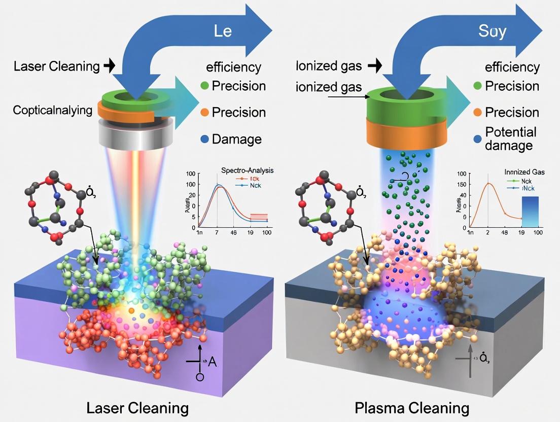
This article provides a comprehensive, science-driven comparison between laser and plasma cleaning technologies for optical components, tailored for researchers and scientists.
Laser Cleaning vs. Plasma Cleaning for Optical Components: A Scientific Comparison for Precision Applications
Abstract
This article provides a comprehensive, science-driven comparison between laser and plasma cleaning technologies for optical components, tailored for researchers and scientists. It explores the fundamental principles of each method, detailing their specific mechanisms for contaminant removal on surfaces like lenses, mirrors, and filters. The content covers critical application methodologies, process optimization strategies, and troubleshooting for high-stakes environments. A direct, evidence-based comparison equips professionals in biomedical and clinical research to select the optimal cleaning technique for enhancing optical performance, ensuring experimental integrity, and improving device reliability.
Understanding the Core Principles of Laser and Plasma Cleaning
Laser cleaning and plasma cleaning represent two advanced, dry techniques for decontaminating surfaces, each operating on distinct physical principles and suited for different applications. Laser cleaning utilizes focused pulsed laser beams to selectively ablate contaminants through a process of ablative photodegradation, whereby the energy of photons is absorbed, breaking chemical bonds in the surface material [1]. In contrast, plasma cleaning employs ionized gas to remove organic matter through chemical reactions and physical sputtering, often at a microscopic level [1] [2]. Within the context of optical components research, where preserving nanoscale surface integrity and optical performance is paramount, the choice between these methods is critical. This guide provides an objective, data-driven comparison of laser and plasma cleaning technologies, drawing on recent experimental studies to delineate their mechanisms, efficacy, and optimal use cases for researchers and scientists.
Principles of Operation
Laser Cleaning and Ablative Photodegradation
Laser cleaning is a non-contact process that removes contaminants by projecting high-energy pulsed laser beams onto a surface. The fundamental mechanism, ablative photodegradation, involves the laser energy being preferentially absorbed by the contaminant layer. This absorption leads to rapid heating, causing the contaminants to undergo vaporization or ablation, effectively breaking chemical bonds and turning them into gas or fine debris [1] [3]. The process is governed by the principle of selective photothermolysis, where the laser parameters—wavelength, pulse duration, and fluence—are tuned to ensure the contaminant's ablation threshold is exceeded while the substrate remains undamaged [4] [5]. For instance, a mid-infrared laser at 2.8 µm is highly absorbed by organic contaminants like epoxy but transmitted through many semiconductor substrates, enabling precise cleaning without substrate damage [5]. The process can involve photothermal, photophysical, and photochemical interactions, with shorter pulses (e.g., picosecond or femtosecond) reducing thermal damage to the underlying material [6].
Plasma Cleaning Mechanisms
Plasma cleaning relies on an ionized gas (plasma) containing a mixture of ions, electrons, and neutral reactive species. This plasma is typically generated by applying a high voltage to a gas like oxygen or argon under low pressure [2] [7]. The cleaning action occurs through two primary mechanisms:
- Chemical Reaction: Reactive species in the plasma, such as oxygen radicals, interact with organic contaminants on the surface, breaking them down into volatile byproducts like CO₂ and H₂O that are then evacuated by the vacuum system [2] [8].
- Physical Sputtering: Ions in the plasma gain energy from the electric field and bombard the surface, physically dislodging contaminants through momentum transfer [8]. Unlike laser cleaning, plasma treatment is often non-selective, uniformly affecting the entire exposed surface. While effective for removing micro- and nanoscale organic contaminants, it can potentially modify the surface chemistry and morphology of the substrate [7] [5].
Comparative Performance Data
The following tables summarize key experimental findings from recent studies, highlighting the performance of each cleaning method in specific applications.
Table 1: Experimental results for laser cleaning applications.
| Material/Cleaning Target | Laser Parameters | Key Results | Source |
|---|---|---|---|
| TC4 Titanium Alloy (Oxide Film) | 1064 nm wavelength, 5.27 J/cm², 300 kHz, Gaussian pulse | Lower surface damage, reduced oxygen content, and lower roughness vs. Flat-top pulse. | [4] |
| HDPE Polymer (Bond Breaking) | 4th Harmonic (266 nm), 3-10 mJ pulse energy, 20 Hz | Most effective at directly breaking C-H bonds, evident from Hα peak at 656.3 nm; minimal ablation. | [9] |
| Silicon Photonics (Epoxy Contaminant) | 2.8 µm wavelength, short pulses | Selective removal of organic epoxy without damaging the underlying silicon substrate. | [5] |
Table 2: Experimental results for plasma cleaning applications.
| Material/Cleaning Target | Plasma Parameters | Key Results | Source |
|---|---|---|---|
| Chemically Coated Optical Components (Organic Contaminants) | Low-pressure oxygen/argon RF plasma | Restored optical transmittance, quantitative relationship between functional groups and transmittance established. | [2] [8] |
| Silicon Carbide (SiC) Surface | Oxygen plasma | Reduced surface roughness from 1.090 nm to 0.055 nm. | [8] |
| Gold Mirror (Carbon Contamination) | RF Plasma | Efficiently removed carbon contaminants and restored original optical performance without secondary contamination. | [8] |
Table 3: Direct comparison of laser and plasma cleaning characteristics.
| Feature | Laser Cleaning | Plasma Cleaning |
|---|---|---|
| Process Mechanism | Focused laser energy (Ablative photodegradation) | Ionized gas interaction (Chemical/Physical) |
| Selectivity | High (Wavelength-dependent absorption) | Low (Blanket treatment) |
| Suitable Contaminants | Rust, coatings, paints, oxides, organic particles [1] [3] | Organic films, micro-particles, carbon contamination [2] [8] |
| Spatial Precision | High (Can be localized to sub-micron spots) | Low (Treats entire exposed surface) |
| Impact on Surface | Minimal substrate damage if tuned correctly; can alter roughness [4] | Can activate surface, improve adhesion, risk of over-etching or surface modification [7] [5] |
| Throughput | Fast for localized cleaning; slower for large areas | Slower for large areas, but good for batch processing of small parts |
| Environmental Impact | Dry process, no chemicals, minimal waste [3] | Low waste generation, uses process gases [7] |
Experimental Protocols
Protocol: Laser Cleaning of Oxide Films on TC4 Titanium Alloy
This protocol is adapted from a study investigating the removal of oxide films using different laser spot patterns [4].
- 1. Sample Preparation: Cut TC4 titanium alloy into 25 mm × 25 mm × 3 mm samples. Clean surfaces to remove any gross contamination. Characterize the native oxide film (approx. 10 µm thick) using Scanning Electron Microscopy (SEM) and metallurgical microscopy.
- 2. Laser Setup:
- Laser Type: Pulsed fiber laser (e.g., 1064 nm wavelength).
- Spot Patterns: Compare Gaussian and Flat-top pulse profiles.
- Key Parameters: Set laser energy density to 5.27 J/cm², repetition frequency to 300 kHz, and scanning speed to 6000 mm/s. The spot diameter is typically 130 µm.
- Equipment Configuration: Mount the laser output on an industrial robot. Use a scanning galvanometer system with a focusing lens to direct the beam across the sample surface in a pre-programmed path.
- 3. Cleaning Procedure: Irradiate the sample surface with the laser according to the set parameters. The laser beam is scanned over the surface to ensure full coverage of the target area.
- 4. Post-Cleaning Analysis:
- Microscopy: Use SEM to examine surface micromorphology and confirm oxide removal.
- Elemental Analysis: Employ Energy Dispersive X-ray Spectroscopy (EDS) with SEM to measure oxygen content on the cleaned surface versus an untreated control.
- Surface Roughness: Quantify using a profilometer or roughness-measuring instrument (e.g., Mitutoyo SJ-140).
Protocol: Low-Pressure Plasma Cleaning of Optical Coatings
This protocol is based on a study that combined experiments and molecular dynamics simulations to clean organic contaminants from sol-gel SiO₂ chemical coatings [2] [8].
- 1. Sample Preparation: Prepare chemical-coated fused silica samples using a dip-coating method with a sol-gel SiO₂ solution. Apply a controlled organic contamination layer to the coated surface.
- 2. Plasma Reactor Setup:
- Reactor Type: Low-pressure capacitive-coupled RF plasma system.
- Gas Composition: Use oxygen (O₂) or argon (Ar) as the process gas.
- Key Parameters: Optimize discharge power and gas pressure based on Langmuir probe measurements to achieve desired plasma potential, ion density, and electron temperature.
- 3. Cleaning Procedure: Place the contaminated sample inside the plasma reactor chamber. Evacuate the chamber to low pressure. Introduce the process gas and ignite the plasma. Treat the sample for a predetermined duration.
- 4. Post-Cleaning Analysis:
- Optical Performance: Measure the transmittance of the optical component at the target wavelength (e.g., 355 nm) to quantify recovery.
- Surface Cleanliness: Use techniques like X-ray Photoelectron Spectroscopy (XPS) to characterize the removal of organic functional groups.
- Molecular Dynamics Simulation: Complement experimental results with a Reactive Force Field (ReaxFF) model to simulate the interaction between plasma species and organic contaminants at the atomic scale, revealing reaction mechanisms.
Signaling Pathways and Workflows
The following diagram illustrates the fundamental decision-making workflow for selecting between laser and plasma cleaning, based on the nature of the contamination and the substrate.
The Scientist's Toolkit: Essential Research Reagents & Materials
Table 4: Key equipment and materials for laser and plasma cleaning research.
| Item | Function/Application | Example Use Case |
|---|---|---|
| Pulsed Fiber Laser (1064 nm) | Primary energy source for ablation; nanosecond pulses offer a balance of cost and effectiveness for many materials. | Removing oxide films from titanium alloys [4]. |
| Mid-IR Laser (2.8-3 µm) | Selectively targets organic contaminants due to strong absorption by O-H and C-H bonds, while transmitting through semiconductors. | Cleaning epoxy from sensitive silicon photonics dies without substrate damage [5]. |
| Low-Pressure RF Plasma Reactor | Generates low-temperature plasma for contaminant removal via chemical reactions and physical sputtering in a controlled vacuum environment. | Removing organic contamination from large-aperture optical components with chemical coatings [2] [8]. |
| Langmuir Probe | Diagnostic tool for characterizing plasma parameters (e.g., electron temperature, ion density) within the reactor. | Optimizing plasma discharge power and gas pressure for efficient cleaning [8]. |
| Sol-Gel SiO₂ Coating | A common, research-relevant chemical coating for optical components, susceptible to organic contamination. | Used as a standardized substrate for testing and optimizing cleaning protocols for optics [8]. |
| Scanning Electron Microscope (SEM) | For high-resolution imaging of surface morphology before and after cleaning to assess effectiveness and substrate damage. | Analyzing the micromorphology and elemental composition (via EDS) of a cleaned TC4 titanium alloy surface [4]. |
| Spectrometer (LIBS/OES) | Laser-Induced Breakdown Spectroscopy or Optical Emission Spectroscopy for in-situ monitoring of the ablation/cleaning process and elemental analysis. | Monitoring the presence of Hα peaks during laser-induced HDPE bond breaking [9] or analyzing plasma species. |
For the researcher in optics and photonics, the choice between laser and plasma cleaning is not a matter of superiority but of strategic application. Laser cleaning excels in precision, offering targeted removal of specific contaminants—from thick oxides on metals to epoxy droplets on photonic integrated circuits—with minimal impact on the surrounding substrate [4] [5]. Its principle of ablative photodegradation provides unparalleled control. Plasma cleaning, conversely, offers comprehensive uniformity, effectively eliminating nanoscale organic films and activating surfaces across entire components, making it ideal for preparing surfaces for bonding or restoring the transmittance of large optics [2] [8]. The experimental data and protocols outlined in this guide provide a foundation for making an evidence-based selection. Ultimately, integrating both technologies into a research or production workflow may provide the most versatile solution, leveraging the strengths of each to meet the extreme cleanliness and integrity demands of next-generation optical components.
In the realm of high-precision optical systems, such as those found in intense laser facilities and inertial confinement fusion research, the performance and longevity of large-aperture optical components are critically dependent on surface cleanliness. Organic contamination on surfaces like anti-reflective or high-reflective coatings can lead to irreversible damage and rapid degradation of optical performance under laser irradiation, reducing the laser damage threshold by approximately 60% [8]. For optical components requiring atomic-level precision, two advanced cleaning technologies have emerged as principal contenders: plasma cleaning and laser cleaning. Plasma cleaning utilizes an ionized gas containing reactive species (ions, electrons, and neutral particles) to remove contaminants at a molecular level, while laser cleaning employs concentrated laser beams to vaporize or ablate unwanted materials through rapid thermal interactions [1] [7].
The selection between these methods represents a significant technical decision for researchers and optical engineers. Plasma technology operates through chemical reactions between reactive plasma species and surface contaminants, effectively breaking them down into volatile byproducts [10]. Laser cleaning, conversely, relies primarily on photophysical and photothermal mechanisms where pulsed laser energy is absorbed by the contamination layer, leading to its removal through vaporization, thermal stress, or explosive evaporation [11] [12]. For optical components with delicate chemical coatings and extreme performance requirements, understanding the atomic-level interactions of these cleaning processes is essential for optimizing cleaning protocols and preventing substrate damage.
Fundamental Principles and Mechanisms
Plasma Cleaning: Atomic-Level Interactions
Plasma cleaning operates through the generation of partially ionized gas containing a complex mixture of reactive species including electrons, positive ions, neutral atoms, molecules in excited states, and UV light [13] [8]. When these species interact with contaminated surfaces, multiple atomic-level processes occur simultaneously. The reactive particles collide with organic contaminants, transferring energy and breaking chemical bonds through radical-driven pathways [8]. Simultaneously, UV radiation from the plasma contributes to molecular bond breaking, while ion bombardment provides physical energy transfer that disrupts contaminant layers.
The efficacy of plasma cleaning is governed by key parameters including discharge power, gas composition, pressure, and treatment duration. Experimental studies combining Langmuir probe measurements and emission spectroscopy have demonstrated that these parameters directly influence plasma potential, ion density, and electron temperature, which in turn determine cleaning efficiency [8]. Reactive molecular dynamics (RMD) simulations have revealed that the primary cleaning processes occur on nanosecond timescales at atomic spatial scales, with the reactive species in the plasma (particularly oxygen radicals in oxygen-based plasmas) chemically reacting with carbon-based contaminants to form volatile reaction products such as CO and CO₂ that are subsequently removed from the surface [8].
Laser Cleaning: Fundamental Mechanisms
Laser cleaning employs high-energy laser pulses to remove contaminants through several interconnected mechanisms. The primary removal mechanisms include:
Ablation Gasification Effect: When a high-energy laser beam strikes a contaminant layer, the absorbed energy causes rapid temperature increase exceeding the material's gasification point, leading to instantaneous vaporization and removal [11]. During this process, the vaporized material and surrounding air can be ionized to form plasma, which generates a high-pressure shock wave that further contributes to contaminant removal [11] [12].
Vibration Stripping Effect: The rapid thermal expansion of the contaminant layer creates thermal stress that exceeds the adhesion force between the contaminant and substrate, causing mechanical detachment [11]. Additionally, interference patterns from reflected laser beams within the contaminant layer create high-energy resonant waves that accelerate removal [11].
Explosion Stripping Effect: Moisture or air trapped in pores and gaps of the contaminant layer rapidly expands when heated by the laser, generating pressure that overcomes adhesion forces and causes explosive removal of the material [11].
The laser cleaning process is governed by precise parameter control, with energy density needing to remain between two critical thresholds: the contamination removal threshold and the substrate damage threshold [12]. This threshold effect enables self-limiting cleaning where contaminants are removed without damaging the underlying substrate.
Comparative Analysis: Plasma vs. Laser Cleaning
Technical Performance Comparison
Table 1: Technical Performance Comparison of Plasma and Laser Cleaning
| Parameter | Plasma Cleaning | Laser Cleaning |
|---|---|---|
| Cleaning Mechanism | Chemical reaction with reactive species & ion bombardment [13] [8] | Thermal ablation, vibration stripping, & shock waves [11] [12] |
| Spatial Resolution | Macroscopic to microscopic (uniform coverage) [10] | High precision (can target specific areas) [7] |
| Contaminant Types | Organic residues, micro-particles, microbial contaminants [13] [8] | Oxide films, paint layers, rust, biofilms [1] [11] [14] |
| Surface Modification | Activates surface, increases surface energy, improves wettability [13] [10] | Can alter surface roughness, minimal chemical modification [11] [7] |
| Penetration Capability | Reaches complex geometries and tight spots [10] | Line-of-sight process, limited for hidden areas [7] |
Table 2: Process Characteristics and Applications Comparison
| Characteristic | Plasma Cleaning | Laser Cleaning |
|---|---|---|
| Operating Environment | Low-pressure vacuum chambers or atmospheric pressure [13] [10] | Ambient atmosphere, typically no enclosure required [1] |
| Typical Treatment Time | 2-120 seconds [13] | Varies with contamination thickness and area [12] |
| Suitable Materials | Metals, plastics, ceramics, glass, elastomers [13] | Metals, ceramics, polymers, artworks [1] [11] |
| Primary Industries | Semiconductor, medical devices, optics, electronics [13] [8] | Aerospace, automotive, marine, art conservation [1] [11] |
| Environmental Impact | Low, minimal chemical usage [13] [10] | Low, minimal waste generation [11] |
Applications in Optical Components Research
For optical components research, each cleaning method offers distinct advantages depending on the specific application requirements:
Plasma Cleaning Applications: Plasma cleaning excels in applications requiring molecular-level cleanliness and surface activation without material removal. Studies have demonstrated its effectiveness in restoring the optical transmittance of large-aperture optical components with chemical coatings by removing organic contaminants that cause laser-induced damage [8]. The technology is particularly valuable for cleaning delicate optical components with complex geometries where uniform coverage is essential. Research has shown that low-pressure oxygen plasma can effectively remove carbon-based contaminants from optical surfaces, restoring near-baseline optical performance through radical-driven pathways [8].
Laser Cleaning Applications: Laser cleaning has proven effective for removing specific contaminant layers from optical components, with research focusing on real-time monitoring using techniques like laser-induced breakdown spectroscopy (LIBS) to ensure optimal cleaning without substrate damage [14]. The precision of laser cleaning allows for selective removal of contaminants from specific areas without affecting surrounding regions, making it valuable for delicate optical components where controlled material removal is required. Studies have successfully demonstrated laser cleaning of various contaminants while preserving the substrate's structural integrity [11].
Experimental Protocols and Methodologies
Plasma Cleaning Experimental Protocol for Optical Components
Objective: To remove organic contaminants from chemical-coated optical components while restoring optical transmittance and laser damage resistance.
Materials and Equipment:
- Low-pressure plasma cleaning system with RF power source
- Vacuum chamber with gas flow control system
- Langmuir probe for plasma characterization
- Optical emission spectrometer
- Reference optical components with sol-gel SiO₂ chemical coatings
- Oxygen and argon gas sources
Methodology:
- Sample Preparation: Prepare chemical-coated fused silica samples using dip-coating method with sol-gel SiO₂ at 355 nm wavelength. Maintain consistent coating parameters: 25°C temperature, 85 mm/min pull speed, and post-treatment with ammonia and HMDS for 24 hours [8].
Plasma System Setup:
- Place samples in vacuum chamber and evacuate to appropriate pressure
- Introduce oxygen or oxygen-argon gas mixture at controlled flow rates
- Apply RF power (typically 13.56 MHz) to generate capacitive-coupled discharge
- Maintain low-pressure environment (typically 10-100 mTorr) [8]
Process Monitoring:
- Use Langmuir probe to measure plasma potential, ion density, and electron temperature
- Employ optical emission spectroscopy to identify reactive species concentrations
- Monitor discharge power (typically 100-500W) and gas pressure as critical parameters [8]
Quality Assessment:
- Measure optical transmittance before and after cleaning
- Characterize surface morphology using SEM/EDS analysis
- Evaluate laser damage threshold recovery
- Assess cleaning uniformity across large apertures
Key Parameters from Recent Studies: Recent research has established that optimal cleaning occurs within specific process windows: discharge power significantly affects electron temperature and ion density, while gas composition influences the types of reactive species generated. Molecular dynamics simulations have revealed that bombardment energy and ion flux are critical factors in the efficiency of organic contaminant removal [8].
Laser Cleaning Experimental Protocol with LIBS Monitoring
Objective: To remove marine biofilm layers from aluminum alloy surfaces while monitoring cleaning quality in real-time and preventing substrate damage.
Materials and Equipment:
- Nanosecond pulsed fiber laser (200W maximum power, 1064 nm wavelength)
- Galvanometer scanning system
- Laser-Induced Breakdown Spectroscopy (LIBS) system with spectrometer (300-800 nm range)
- 6061 aluminum alloy samples with marine biofilm layers
- Scanning Electron Microscope with EDS analyzer
- Digital microscope for surface morphology examination
Methodology:
- Sample Preparation:
- Prepare 6061 aluminum alloy specimens (150 mm × 40 mm × 2 mm)
- Immerse in marine environment for 3 months to develop natural biofilm layers
- Characterize initial biofilm thickness (40-65 μm for hard attachments, 20-50 μm for EPS layers) [14]
Laser Cleaning Setup:
- Configure laser parameters: pulse width (30-240 ns), repetition rate, spot size
- Set scanning pattern ('S' trajectory) with rectangular scanning path (15 mm × 15 mm)
- Adjust laser power (typically 20-160W based on contamination type) [14]
LIBS Monitoring Implementation:
- Position fiber optic probe 80 mm from workpiece surface
- Collect plasma spectra during cleaning process (300-800 nm wavelength range)
- Monitor characteristic elemental peaks (C, O, Al, Ca, Mg) [14]
- Establish "reference spectrum" for optimal cleaning endpoint determination
Process Optimization:
- Calculate Pearson correlation coefficient between acquired spectra and reference spectrum
- Adjust laser parameters based on real-time spectral feedback
- Determine optimal cleaning parameters through regression fitting of spectral data [14]
Post-Cleaning Analysis:
- Perform EDS analysis to verify elemental composition changes
- Examine surface morphology using SEM
- Assess cleaning completeness and substrate damage
Table 3: Research Reagent Solutions for Plasma and Laser Cleaning Experiments
| Reagent/Material | Function | Application Context |
|---|---|---|
| Sol-gel SiO₂ coating | Creates uniform chemical coatings on optical components | Plasma cleaning studies on model contaminated optics [8] |
| Oxygen and Argon gases | Process gases for plasma generation | Creating reactive species in plasma cleaning [8] |
| Ammonia and HMDS | Post-treatment reagents for chemical coatings | Enhancing coating durability before contamination studies [8] |
| Marine biofilm layers | Representative organic contamination | Testing laser cleaning effectiveness on natural biofilms [14] |
| Langmuir probe | Measures plasma parameters (potential, density, temperature) | Characterizing plasma conditions during cleaning [8] |
| LIBS spectrometer | Real-time monitoring of elemental composition | Determining cleaning endpoints during laser processes [14] |
Visualization of Cleaning Mechanisms and Processes
Diagram 1: Plasma cleaning process workflow showing the sequence from gas introduction to surface cleaning.
Diagram 2: Laser cleaning process with real-time LIBS monitoring and feedback control system.
Plasma and laser cleaning technologies offer complementary approaches for addressing contamination challenges in optical components research. Plasma cleaning excels in applications requiring molecular-level cleanliness, surface activation, and uniform coverage of complex geometries, particularly for removing organic contaminants from delicate optical coatings. The atomic-level interactions between reactive plasma species and contaminants follow radical-driven pathways that efficiently restore optical performance without damaging underlying substrates.
Laser cleaning provides high-precision removal of specific contaminant layers with real-time monitoring capabilities, making it particularly valuable for applications where controlled material removal is essential. The integration of LIBS monitoring enables precise endpoint detection and optimization of cleaning parameters, ensuring complete contaminant removal while preserving substrate integrity.
For optical components research, the selection between these technologies depends on specific application requirements, including the nature of contaminants, substrate sensitivity, geometrical considerations, and desired post-cleaning surface properties. Both techniques offer environmentally friendly alternatives to traditional chemical cleaning methods and continue to evolve through advanced process monitoring and control methodologies. As research progresses, the combination of experimental approaches with molecular dynamics simulations provides increasingly detailed understanding of the fundamental interactions at the atomic level, enabling further optimization of these critical cleaning technologies for high-performance optical systems.
The performance and longevity of optical components are critically dependent on surface cleanliness. Contaminants such as organic residues, particles, and oxides can severely compromise optical performance by increasing light scattering, creating hot spots through radiation absorption, and reducing laser-induced damage thresholds [15] [16]. In research environments, particularly those involving intense laser systems like inertial confinement fusion facilities, surface contaminants on optical components can reduce laser damage thresholds by approximately 60% [8]. Traditional cleaning methods, including mechanical grinding, chemical solvents, and ultrasonic cleaning, often present challenges such as difficulty in localization, high residue, low efficiency, environmental pollution, and health hazards [17]. This comparison guide objectively evaluates two advanced cleaning technologies—laser cleaning and plasma cleaning—for addressing these contaminant targets on optical surfaces, providing researchers with experimental data and protocols to inform method selection.
Plasma Cleaning
Plasma cleaning is a surface treatment process that utilizes ionized gas (plasma) containing active species such as ions, electrons, and neutral particles to remove contaminants from various materials [7]. The process is initiated by applying a high voltage to a gas, leading to ionization and the creation of reactive ions and free radicals that interact with surface contaminants, causing decomposition [7]. This technology not only cleans surfaces but can also modify surface properties to improve adhesion and wettability for subsequent treatments [7]. Plasma cleaning is particularly noted for its effectiveness on intricate geometries and micro-scale contaminants, making it suitable for delicate optical components [7].
Laser Cleaning
Laser cleaning employs concentrated laser beams to remove unwanted materials from surfaces through thermal interaction [7]. The process directs a high-powered laser beam onto the surface, where the energy is absorbed by contaminants, causing them to vaporize or ablate [7]. This method leaves minimal residue as contaminants are converted into gas or fine debris that can be easily removed [7]. Laser cleaning is recognized for its precision, speed, and effectiveness in dealing with heavily soiled surfaces, including rust, paint, and other tough contaminants on metals [7]. The technology is particularly advantageous for its non-invasive nature, which helps maintain the integrity of the base material [7].
Comparative Performance Analysis
Removal Efficacy for Primary Contaminant Types
Organic Residues: Plasma cleaning excels in removing organic contamination through a chemical reaction process where plasma's UV energy breaks organic bonds on surface contaminants, causing them to volatilize [18]. Experimental studies on low-pressure plasma cleaning of organic contamination from chemically coated surfaces demonstrate that oxygen plasma effectively removes organic contaminants from optical components, restoring near-baseline optical performance through radical-driven pathways [2] [8]. Laser cleaning also effectively removes organic contaminants, though its mechanism is primarily thermal rather than chemical.
Particles and Dust: Laser cleaning shows superior performance for removing particulate contamination through its ablation mechanism. The focused laser energy effectively dislodges and removes particles from surfaces without contact [7]. Plasma cleaning can remove particles but may be less effective for larger, non-adhered particulates compared to laser methods.
Oxides: Laser cleaning has proven particularly effective for oxide removal from metal surfaces. The technology is widely used for rust removal from various metal substrates [7] [18]. Plasma cleaning can remove oxides but may be less efficient for thicker oxide layers compared to laser cleaning.
Table 1: Contaminant Removal Efficacy Comparison
| Contaminant Type | Plasma Cleaning Efficacy | Laser Cleaning Efficacy | Notes |
|---|---|---|---|
| Organic Residues | High (chemical breakdown) | Medium-High (thermal ablation) | Plasma uses radical-driven pathways [8] |
| Fine Particles | Medium | High (non-contact removal) | Laser effective for non-adhered particulates [7] |
| Oxides | Medium | High (efficient ablation) | Laser preferred for thick oxide layers [7] |
| Biofilms | Limited data | High (proven efficacy) | Laser successfully removes marine biofilms [14] |
| Micro-scale Contaminants | High (excellent for intricate geometries) | Medium (depends on laser focus) | Plasma superior for complex microstructures [7] |
Process Parameters and Experimental Results
Plasma Cleaning Parameters: Experimental studies on low-pressure plasma cleaning have identified key parameters that influence cleaning efficacy. Research combining experimental and molecular dynamics studies has shown that discharge power, gas pressure, plasma potential, ion density, and electron temperature significantly affect cleaning performance [2] [8]. Optimal parameters for organic contaminant removal from optical components typically involve oxygen or argon gas mixtures, with specific combinations of these parameters determined through Langmuir probe and emission spectrometer measurements [8].
Laser Cleaning Parameters: Laser cleaning effectiveness is predominantly determined by process parameters including laser power, pulse width, frequency, and scanning speed [17]. Experimental research on removing Al metal layers from ceramic substrate surfaces demonstrated that a laser with power of 120 W, pulse width of 200 ns, frequency of 240 kHz, and speed of 6000 mm/s could effectively remove a 50 μm Al metal layer in a single cleaning cycle without damaging the ceramic substrate [17]. Studies on marine biofilm removal from aluminum alloy surfaces utilized nanosecond pulsed fiber lasers with 1064 nm wavelength, with effectiveness monitored through laser-induced breakdown spectroscopy (LIBS) [14].
Table 2: Quantitative Performance Metrics from Experimental Studies
| Parameter | Plasma Cleaning Results | Laser Cleaning Results | Measurement Methods |
|---|---|---|---|
| Cleaning Rate | Varies with parameters; can reduce carbon coating thickness by 35% in 6000s [8] | Removes 50μm Al layer in single pass at 6000mm/s [17] | Thickness measurement, SEM |
| Surface Roughness Impact | Can reduce roughness (e.g., SiC from 1.090 nm to 0.055 nm) [8] | Increases roughness (Ra from 9.426 µm to 13.846 µm with power increase) [17] | Surface roughness tester, AFM |
| Optical Performance Recovery | Restores near-baseline transmittance [8] | Improved surface quality for coating adhesion [17] | Spectrometry, LIBS [14] |
| Spatial Resolution | Excellent for complex geometries [7] | High precision (spot diameter ~0.2 mm) [17] | Microscopy, surface analysis |
| Substrate Damage Risk | Low (non-abrasive) [19] | Medium (thermal damage risk at high power) [17] | SEM, damage threshold testing |
Experimental Protocols and Methodologies
Plasma Cleaning Experimental Protocol
Apparatus Setup: The experimental setup for low-pressure plasma cleaning typically consists of a capacitive-coupled discharge chamber, radio-frequency (RF) power supply (often 13.56 MHz), gas supply system (oxygen, argon, or mixtures), vacuum system, and diagnostic tools including Langmuir probes and emission spectrometers [8].
Sample Preparation: Optical components with chemical coatings (e.g., sol-gel SiO₂ anti-reflective coatings) are prepared using dip-coating methods. Prior to cleaning, samples may be artificially contaminated with standardized organic compounds to ensure consistent testing conditions [8].
Cleaning Procedure:
- Place samples in the plasma chamber and evacuate to base pressure (typically 10⁻² to 10⁻³ mbar)
- Introduce process gas (oxygen for organic contaminants) at controlled flow rates
- Apply RF power to generate plasma, maintaining desired power density (W/cm³)
- Maintain processing for predetermined duration (varies by contamination level)
- Vent chamber and remove samples for analysis
Analysis Methods: Post-cleaning analysis includes surface morphology examination (SEM, AFM), chemical analysis (XPS, EDS), optical performance measurement (transmittance, reflectance), and laser damage threshold testing [8].
Figure 1: Plasma Cleaning Experimental Workflow
Laser Cleaning Experimental Protocol
Apparatus Setup: Laser cleaning systems typically comprise a nanosecond pulsed fiber laser (e.g., 1064 nm wavelength, 200 W maximum power), computer control system, galvanometer scanner for beam steering, and dust collection system [14] [17]. Additional monitoring equipment such as laser-induced breakdown spectroscopy (LIBS) may be integrated for real-time process monitoring [14].
Sample Preparation: Substrate materials (e.g., aluminum alloy, ceramics with coatings) are prepared according to experimental requirements. For contamination studies, surfaces may be artificially coated with target contaminants of known thickness and composition [14] [17].
Cleaning Procedure:
- Secure sample in processing station
- Set laser parameters (power, pulse width, frequency, scanning speed)
- Program scanning pattern (typically "S" pattern or rectangular path)
- Initiate cleaning process with integrated dust collection
- Monitor process with LIBS or other real-time monitoring if equipped
Analysis Methods: Post-cleaning evaluation includes microscopic examination (optical microscopy, SEM), surface roughness measurement, elemental analysis (EDS), and spectral monitoring to assess cleaning completeness [14] [17].
Figure 2: Laser Cleaning Experimental Workflow
The Scientist's Toolkit: Essential Research Reagents and Materials
Table 3: Key Research Reagent Solutions and Experimental Materials
| Item | Function/Application | Usage Notes |
|---|---|---|
| Oxygen Gas (High Purity) | Process gas for plasma cleaning of organic residues | Promotes radical-driven oxidation of contaminants [2] |
| Argon Gas (High Purity) | Process gas for plasma cleaning; provides physical sputtering | Often used in mixtures with oxygen [8] |
| Sol-Gel SiO₂ Coating | Standardized test substrate for optical coating studies | 29 nm particle size, applied by dip-coating [8] |
| Webril Wipes | Pure cotton wipers for manual cleaning comparison | Hold solvent well, do not dry quickly [15] |
| Optical Grade Solvents | Reference cleaning method (acetone, methanol, isopropanol) | Used for comparative traditional cleaning [15] |
| Langmuir Probe | Plasma characterization (potential, density, electron temperature) | Critical for plasma parameter optimization [8] |
| Emission Spectrometer | Plasma species identification and monitoring | Determines reactive particles in plasma [8] |
| Laser-Induced Breakdown Spectroscopy (LIBS) | Real-time monitoring of laser cleaning process | Analyzes plasma spectra during cleaning [14] |
Application Scenarios and Selection Guidelines
Optimal Technology Selection Based on Contaminant Profile
Plasma Cleaning is Preferred For:
- Delicate optical components with complex geometries or microstructures [7]
- Applications requiring thorough cleaning of organic residues at microscopic scales [7] [8]
- Surface preparation where enhanced adhesion for subsequent coatings is required [7] [19]
- Semiconductor and medical device manufacturing where chemical purity is critical [7] [18]
- Situations where minimal substrate alteration is mandatory [19]
Laser Cleaning is Preferred For:
- Rapid removal of heavy contaminants including oxides and thick coatings [7]
- Larger surfaces requiring localized cleaning of specific areas [7]
- Restoration of metal surfaces and removal of marine biofilms [7] [14]
- Applications where non-contact processing is advantageous [7]
- Environments where chemical solvents are undesirable [18]
Limitations and Constraints
Plasma Cleaning Limitations: The process can be slower than laser cleaning, especially for large surface areas [7]. It requires vacuum systems for low-pressure operation, potentially limiting sample size [8]. The technology may have higher initial setup costs and complexity [7].
Laser Cleaning Limitations: Effectiveness can vary based on material and laser settings, requiring careful parameter optimization [7] [17]. There is potential for uneven cleaning if not properly calibrated [7]. The technology requires a direct line of sight to the surface, limiting accessibility to some complex geometries [18]. At higher power settings, there is risk of thermal damage to substrates [17].
Plasma and laser cleaning technologies offer complementary capabilities for addressing the primary contaminant targets on optical surfaces. Plasma cleaning excels in removing organic residues through chemical mechanisms and is particularly suitable for delicate components with complex geometries. Laser cleaning demonstrates superior performance for removing oxides, particles, and thicker contaminant layers through thermal ablation processes. The selection between these technologies should be guided by the specific contaminant profile, substrate characteristics, and required post-cleaning surface properties. Experimental evidence indicates that both methods can effectively restore optical performance when appropriate parameters are employed, providing researchers with viable alternatives to traditional cleaning methodologies that may involve environmental concerns or inadequate precision. As optical technologies advance toward smaller features and more exacting performance requirements, both plasma and laser cleaning methodologies continue to evolve, offering increasingly sophisticated solutions for surface preparation and contamination management in research environments.
The Critical Role of Surface Cleanliness in Optical Performance and Signal Integrity
In advanced optical systems, from high-power lasers to precision scientific instruments, surface cleanliness is not merely a matter of maintenance but a fundamental determinant of performance and reliability. Contaminants—including organic residues, particulate matter, and oxides—compromise optical performance by increasing light scattering, absorption, and thermal damage susceptibility, while simultaneously degrading signal integrity through increased noise and reduced signal-to-noise ratios. The selection of appropriate cleaning methodologies is therefore a critical consideration in optical system design and maintenance.
This guide provides a scientific comparison of two advanced cleaning technologies—laser cleaning and plasma cleaning—for optical components. Through experimental data and systematic analysis, we objectively evaluate their performance across key parameters including cleaning efficacy, damage threshold, and signal integrity preservation, providing researchers with evidence-based selection criteria.
Laser Cleaning Technology
Laser cleaning employs focused, high-energy laser pulses directed onto contaminated surfaces. The process relies on photothermal and photomechanical mechanisms: laser energy is selectively absorbed by contaminants, causing rapid heating, vaporization, and ablation, while the underlying substrate remains undamaged due to its higher ablation threshold or reflective properties. The process typically uses pulsed lasers with power ranging from 20 to 1,000 watts, with short pulses (nanosecond to femtosecond) enabling precise contaminant removal with minimal thermal diffusion [1] [20].
Plasma Cleaning Technology
Plasma cleaning utilizes partially ionized gas (plasma) containing reactive species (ions, electrons, neutral radicals) to remove surface contaminants through chemical reaction and physical bombardment. In low-pressure systems, radio-frequency (RF) or microwave energy ionizes process gases (e.g., oxygen, argon), generating reactive species that decompose organic contaminants into volatile byproducts (e.g., CO₂, H₂O) while physically dislodging inorganic particulates through ion bombardment. This non-thermal process effectively cleans at atomic levels without damaging temperature-sensitive substrates [8] [21].
Table 1: Fundamental Characteristics of Laser and Plasma Cleaning Technologies
| Parameter | Laser Cleaning | Plasma Cleaning |
|---|---|---|
| Process Mechanism | Photothermal/Photomechanical ablation | Chemical reaction & physical bombardment |
| Energy Source | Focused laser beam (pulsed/continuous) | Ionized gas (RF/microwave excitation) |
| Spatial Resolution | High (µm-mm scale, localized treatment) | Lower (cm-scale, uniform treatment) |
| Process Environment | Ambient air or controlled atmosphere | Low-pressure vacuum or atmospheric |
| Primary Contaminant Removal Mechanism | Vaporization, sublimation | Radical-driven decomposition, sputtering |
Experimental Comparison: Performance Data Analysis
Cleaning Efficacy for Optical Components
Experimental Protocol A (Plasma Cleaning): Researchers prepared chemical-coated fused silica samples (355 nm SiO₂ anti-reflective coatings) with controlled organic contamination. Low-pressure oxygen plasma cleaning was performed using capacitive-coupled RF discharge (13.56 MHz) with varying power (100-500W), pressure (0.1-1.0 Torr), and exposure duration. Cleaning efficacy was quantified through water contact angle measurements, atomic force microscopy (AFM) for surface topography, and spectroscopic ellipsometry for contaminant layer thickness [8] [22].
Experimental Protocol B (Laser Cleaning): Studies evaluated pulsed laser cleaning (fiber lasers, 1064 nm wavelength) on contaminated optical components including mirrors, lenses, and coated substrates. Parameters varied included pulse energy (0.1-10 mJ), repetition rate (1-100 kHz), scan speed, and number of passes. Efficacy was assessed through spectrophotometry (transmittance/reflectance), optical microscopy, and laser-induced damage threshold (LIDT) testing per ISO 21254 [20].
Table 2: Quantitative Cleaning Performance Comparison for Optical Components
| Performance Metric | Laser Cleaning | Plasma Cleaning | Measurement Method |
|---|---|---|---|
| Organic Contaminant Removal Efficiency | >95% for surface layers | >99% for monolayer contaminants | XPS, AFM, contact angle |
| Particulate Removal Efficiency | >90% (size-dependent) | 70-85% (size-dependent) | Optical microscopy, particle counting |
| Surface Roughness Change | Variable: ±0.5-5 nm | Minimal: ±0.1-0.5 nm | Atomic force microscopy (AFM) |
| Processing Speed | 0.1-10 cm²/s (power-dependent) | 0.01-0.5 cm²/s (uniform area) | Timed experimental measurements |
| Transmittance Recovery | 95-98% of baseline | 98-99.5% of baseline | Spectrophotometry (200-1100 nm) |
Impact on Optical Performance and Damage Threshold
Laser-Induced Damage Threshold (LIDT) represents a critical parameter for high-power laser optics, quantifying the maximum laser fluence a component can withstand without damage. Contamination reduces LIDT by creating absorption sites that initiate thermal runaway damage [22].
Experimental Findings: Plasma cleaning demonstrated exceptional performance in restoring LIDT of contaminated optics. For fused silica with organic contamination, low-pressure oxygen plasma treatment restored LIDT to 98.5% of pristine baseline values, compared to 95% recovery with optimized laser cleaning. The radical-driven decomposition mechanism of plasma cleaning completely removes hydrocarbon films without altering substrate morphology, thereby preserving intrinsic damage resistance [8] [22].
Table 3: Optical Performance Recovery After Cleaning Treatments
| Optical Parameter | Contaminated State | Post-Laser Cleaning | Post-Plasma Cleaning | Test Methodology |
|---|---|---|---|---|
| Transmittance at 355 nm (%) | 89.5±0.8 | 95.2±0.3 | 99.1±0.2 | Spectrophotometry |
| Wavefront Error (λ RMS @ 633 nm) | 0.25λ | 0.18λ | 0.11λ | Interferometry |
| LIDT (J/cm² @ 355 nm, 8 ns) | 8.2±1.1 | 14.5±0.8 | 15.8±0.5 | ISO 21254-1 |
| Scatter Loss (%) | 3.8±0.5 | 1.2±0.3 | 0.5±0.1 | Integrating sphere |
Diagram 1: Decision Framework for Selecting Optical Cleaning Methodology. Plasma cleaning is preferred for high-LIDT requirements and organic contaminants, while laser cleaning excels for thick inorganic contaminants and geometrically simple surfaces.
Research Reagent Solutions: Experimental Materials
Table 4: Essential Research Materials for Optical Cleaning Experiments
| Material/Equipment | Function in Research | Specification Guidelines |
|---|---|---|
| Low-Pressure Plasma System | RF (13.56 MHz) or microwave plasma generation for contamination removal | Chamber base pressure: <10⁻³ Torr; Power: 100-1000W; Gas control: O₂, Ar, H₂, CF₄ |
| Pulsed Laser Source | Contaminant ablation using controlled laser parameters | Wavelength: 1064 nm, 532 nm, 355 nm; Pulse duration: ns-fs; Fluence: 0.1-10 J/cm² |
| Optical Test Samples | Substrates for cleaning efficacy quantification | Fused silica, BK7, coated optics (AR/HR); Size: 25-50mm diameter; Surface quality: λ/4-λ/10 |
| Characterization Tools | Pre- and post-cleaning surface analysis | Spectrophotometer (190-2500nm), AFM (atomic resolution), contact angle goniometer |
| Process Gases | Plasma medium for reactive species generation | Research grade O₂ (99.999%), Ar (99.999%), forming gas (H₂/N₂) |
Application-Specific Implementation Guidelines
High-Power Laser Optics
For optical components in intense laser systems (e.g., ICF facilities), where organic contamination reduces laser damage threshold, low-pressure oxygen plasma cleaning demonstrates superior performance. Experimental results show plasma treatment completely restores optical performance of contaminated components, with transmittance returning to baseline and LIDT recovering to pristine levels [8] [22]. The radical-driven pathway of oxygen plasma efficiently removes hydrocarbon films without inducing surface defects that initiate laser damage.
Precision Optical Coatings
Laser cleaning provides advantages for removing particulate contaminants and surface films from coated optics without damaging delicate multilayer structures. The selective absorption特性 enables precise removal of specific contaminant layers while preserving underlying coating integrity. Pulsed laser systems with flat-top beam profiles and optimized wavelength selection (e.g., 355 nm for silica coatings) demonstrate particular effectiveness for precision cleaning applications [20].
Complex Geometry Components
Plasma cleaning excels for components with intricate geometries, internal channels, or complex surface topography where line-of-sight methods are inadequate. The omnidirectional nature of plasma distribution ensures uniform treatment of all exposed surfaces, reaching areas inaccessible to laser beams. This makes plasma particularly suitable for optical assemblies with microstructures and components with high aspect ratio features [7] [21].
The selection between laser and plasma cleaning technologies represents a critical decision point in optical system development and maintenance, with significant implications for performance, reliability, and lifetime.
Plasma cleaning demonstrates distinct advantages for applications requiring atomic-level cleanliness, delicate surface preservation, and complex geometry treatment. Its chemical reaction mechanism enables complete removal of organic monolayers without substrate damage, making it particularly valuable for high-LIDT optics and precision components where surface integrity is paramount.
Laser cleaning offers superior capabilities for rapid removal of thick contaminants, localized treatment, and in-situ applications. Its precision ablation characteristics make it ideal for selective contaminant removal, restoration of historical optics, and processing of large-area components where specific regions require treatment.
For researchers and optical engineers, this comparative analysis provides evidence-based selection criteria aligned with specific application requirements, enabling optimized cleaning protocol development for enhanced optical performance and signal integrity across diverse scientific and industrial applications.
Methodologies and Specific Applications for Optical Components
In the realm of optical components research, the integrity of surfaces is paramount. Contaminants—whether organic films, particulate matter, or oxidation layers—can significantly degrade optical performance by increasing scatter, absorption, and laser-induced damage threshold (LIDT). For researchers and drug development professionals relying on high-precision optical systems, the choice of cleaning methodology directly impacts experimental reproducibility, data accuracy, and component lifetime. This guide provides an objective, data-driven comparison between two advanced cleaning techniques: laser cleaning and plasma cleaning.
Laser cleaning operates through selective ablation, utilizing focused, high-energy laser beams to vaporize contaminants without damaging the underlying substrate [18] [23]. Its counterpart, plasma cleaning, employs an ionized gas to chemically break down and physically sputter surface contaminants through a micro-sandblasting effect [18] [24]. Both are non-contact, solvent-free processes sought after as alternatives to abrasive and chemical techniques, yet their mechanisms, applications, and outcomes differ substantially [24] [25]. This article situates these technologies within a broader thesis on optical component preservation, providing the quantitative data and experimental protocols necessary for informed methodological selection in scientific settings.
Fundamental Mechanisms: A Comparative Workflow
The core processes of laser and plasma cleaning involve fundamentally different physical principles. The following diagrams illustrate the sequential workflow for each technology.
Laser Cleaning Mechanism
Diagram Title: Laser Cleaning Workflow
Laser cleaning relies on photothermal interaction. A pulsed laser beam is directed onto the surface, and its energy is preferentially absorbed by the contaminant layer, causing rapid thermal heating [18] [24]. This leads to ablation, where contaminants are vaporized or turned into plasma and ejected from the surface [18]. The process is governed by selective ablation thresholds, allowing for the removal of the contaminant while preserving the underlying optical substrate [25].
Plasma Cleaning Mechanism
Diagram Title: Plasma Cleaning Workflow
Plasma cleaning uses chemically reactive ionized gas. The plasma, often generated from gases like argon or oxygen, produces reactive ions, electrons, and neutral particles that interact with the surface [18] [7]. These species break down contaminants through chemical reactions and physical sputtering. The process also involves UV radiation that breaks organic bonds, leading to the volatilization of contaminants and their removal from the surface [18]. This process can also activate the surface, enhancing its wettability and adhesion properties [7].
Performance Comparison: Quantitative Data
The following tables summarize key performance metrics and characteristics for laser and plasma cleaning, based on published industrial data and research findings.
Table 1: Core Performance Metrics for Laser vs. Plasma Cleaning
| Performance Metric | Laser Cleaning | Plasma Cleaning | Experimental Measurement Method |
|---|---|---|---|
| Typical Cleaning Speed | Very Fast (galvo scanning) [24] [25] | Slower (mechanical gantry movement) [24] [25] | Throughput (cm²/min) via timed area cleaning |
| Weld Strength after Cleaning | 3000-5000 gf (Cpk ~2) [24] [25] | < 1000 gf (Cpk < 1) [24] [25] | Tensile pull test on cleaned weld joints |
| Surface Roughness Impact | Variable; can be controlled [7] | Slight increase; activates surface [7] | Post-cleaning profilometry or AFM |
| Residue Post-Cleaning | Minimal (vaporization) [24] | Potential for carbonized residues [24] [25] | Visual inspection, SEM, or EDS analysis |
Table 2: Process Characteristics and Material Compatibility
| Characteristic | Laser Cleaning | Plasma Cleaning |
|---|---|---|
| Primary Mechanism | Selective ablation via focused light [18] [24] | Contaminant carbonization via ionized gas [18] [24] |
| Best for Contaminant Types | Rust, oxides, paint, mill scale, oils [18] [24] [20] | Organic films, oils, dust, adhesives [18] [24] [7] |
| Optical Substrate Compatibility | Metals, ceramics, glass [23] [24] | Plastics, metals, ceramics [18] [7] |
| Limitations | Requires line-of-sight; less effective on clear coats [18] [24] | Slower for large areas; may not remove thick oxides [18] [24] [7] |
| Environmental & Safety | Fume extraction needed; no chemicals [23] [25] | Low waste; uses electricity and gas [18] [7] |
Experimental Protocols for Coating Removal
To ensure valid and reproducible results when comparing cleaning technologies, standardized experimental protocols are essential. The following methodologies are adapted from current research practices.
Protocol for Laser-Induced Breakdown Spectroscopy (LIBS) Monitoring
Objective: To perform real-time, in-situ monitoring of the laser cleaning process and precisely determine the endpoint for coating removal.
Background: LIBS is an advanced spectral analysis technique that enables real-time monitoring of laser cleaning quality by analyzing the plasma generated when the laser ablates the surface [14]. It can identify contaminant types and assess substrate damage.
Materials & Setup:
- Laser System: Nanosecond-pulsed fiber laser (e.g., 1064 nm wavelength) [14].
- Spectrometer: Fiber optic spectrometer with a range of 300-800 nm and 0.01 nm accuracy (e.g., SpectraPro HRS-500) [14].
- Positioning: Fiber optic probe fixed at a specific distance (e.g., 80 mm) from the workpiece [14].
- Software: For spectral acquisition and analysis.
Procedure:
- Baseline Acquisition: Before cleaning, acquire a plasma spectrum from an uncleaned area to identify characteristic elemental lines of the contaminant (e.g., Ca, C, O for biofilms) [14].
- Initiate Cleaning & Monitoring: Start the laser cleaning process while simultaneously collecting plasma spectra at a high frequency.
- Spectral Analysis: Monitor the intensity of contaminant-specific spectral lines (e.g., Ca lines for calcareous deposits) and substrate-specific lines (e.g., Al for aluminum alloy optics) [14].
- Endpoint Determination: The cleaning endpoint is identified when the spectral intensities of contaminant elements diminish significantly and the substrate element intensities stabilize at a maximum. This can be quantified using the "reference spectrum" method and Pearson correlation coefficients [14].
Protocol for Post-Cleaning Surface Characterization
Objective: To quantitatively assess the effectiveness and potential collateral effects of the cleaning process on the optical substrate.
Materials & Equipment:
- Scanning Electron Microscope (SEM) (e.g., Quanta 200F) [14].
- Energy Dispersive X-ray Spectroscopy (EDS) detector.
- White Light Interferometer or Atomic Force Microscope (AFM).
- Contact Angle Goniometer.
Procedure:
- Elemental Composition (EDS):
- Compare EDS spectra from pre- and post-cleaned surfaces.
- Quantify the atomic percentage (At.%) of key contaminant elements (e.g., C, O, Ca) and substrate elements [14].
- Successful cleaning is indicated by a drastic reduction in contaminant element signals.
Surface Morphology (SEM):
Surface Roughness:
- Measure surface roughness (Sa, Sq) using a white light interferometer or AFM on multiple cleaned and uncleaned locations.
- Report the average and standard deviation to quantify the impact of the cleaning process on surface topography.
Surface Energy (Goniometer):
- Measure the water contact angle on cleaned and untreated surfaces.
- A decreased contact angle indicates increased surface energy and activation, a common outcome of plasma cleaning [7].
The Scientist's Toolkit: Essential Research Reagents & Equipment
Table 3: Key Equipment and Reagents for Cleaning Research
| Item | Function/Description | Research Application Example |
|---|---|---|
| Nanosecond Pulsed Fiber Laser | High-power (e.g., 200W), 1064 nm wavelength laser source for ablation [14]. | Standard source for laser cleaning and LIBS plasma generation. |
| Galvo Scanner Head | System of ultra-fast rotating mirrors to direct the laser beam [24] [25]. | Enables high-speed, programmable cleaning patterns. |
| Process Gases (Ar, O₂) | High-purity gases used to generate plasma in a plasma cleaner [18] [7]. | Study the effect of plasma chemistry on cleaning efficacy. |
| LIBS Spectrometer | Instrument to collect and analyze plasma emission spectra in real-time [14]. | In-situ monitoring and endpoint detection for laser cleaning. |
| Fume Extraction System | Vacuum and filtration unit (e.g., with HEPA filter) to capture ablated debris [23]. | Essential for operator safety and containment of nanoparticles. |
| Reference Coating Samples | Optically coated substrates (e.g., with HR/AR coatings) with known LIDT [26]. | Benchmarking cleaning methods against a known, sensitive standard. |
Discussion and Research Outlook
The quantitative data and protocols presented herein reveal a clear, application-dependent dichotomy between laser and plasma cleaning. Laser cleaning demonstrates superior speed and effectiveness for removing inorganic contaminants like rust and oxides from metals, making it highly relevant for restoring metallic optical components and mirrors [18] [24]. The availability of real-time monitoring via LIBS is a significant advantage for precision work and automation [14]. Conversely, plasma cleaning excels at decontaminating complex geometries and delicate surfaces, including some plastics, and is unparalleled in its ability to simultaneously clean and activate a surface for subsequent bonding [18] [7].
For the optical components researcher, the choice is not merely about contamination removal but about preserving the functional integrity of the surface. Future research should focus on the application of these techniques on advanced optical coatings, such as multilayer dielectric stacks and metasurfaces, where the laser-induced damage threshold (LIDT) is the ultimate metric of success [27] [26]. The integration of LIBS and other spectroscopic techniques into a closed-loop feedback system represents the frontier of intelligent, adaptive cleaning processes capable of handling the sophisticated and sensitive materials that will define the next generation of optical systems.
In the realm of optical components research, surface cleanliness is not merely a preference but a fundamental requirement for ensuring optimal performance and longevity. Plasma cleaning has established itself as a critical technology for removing organic contaminants and preparing surfaces with nanometer-scale precision. This process utilizes ionized gas to generate energetic ions and reactive radicals that effectively remove contamination from surfaces without damaging the underlying substrate [28]. For optical components, even sub-monolayer organic contaminants can significantly degrade performance by reducing transmittance and lowering laser-induced damage thresholds, making precision cleaning an essential step in manufacturing and maintenance [8].
This guide provides a comprehensive examination of plasma cleaning protocols, with a specific focus on parameters critical for optical components research: gas selection, vacuum environment control, and the underlying reaction mechanisms. Furthermore, we present an objective comparison with laser cleaning technology, supported by experimental data, to equip researchers with the information necessary to select the appropriate cleaning methodology for their specific applications in optical systems, semiconductor manufacturing, and related scientific fields.
Fundamental Principles of Plasma Cleaning
Plasma Generation and Core Mechanisms
Plasma, often referred to as the fourth state of matter, is an ionized gas containing a mixture of electrons, ions, and neutral species [21]. In plasma cleaning systems, this state is typically achieved by applying a high-voltage electric field to a gas within a controlled chamber, leading to ionization and the creation of a reactive plasma environment [28]. The cleaning action occurs through two primary mechanisms that often work synergistically:
- Chemical Reaction: Reactive species generated in the plasma (such as oxygen radicals) interact with organic contaminants, breaking them down into simpler, volatile molecules like carbon dioxide and water vapor that are evacuated from the system [28].
- Physical Bombardment: Energetic ions (such as Ar+) are accelerated toward the surface, where they physically dislodge contaminants through momentum transfer in a process known as sputtering [21].
The balance between these mechanisms depends on process parameters, particularly the selection of process gases, which can be tailored to optimize cleaning for specific contaminant types and substrate materials.
Low-Pressure Versus Atmospheric Plasma Systems
Plasma cleaning systems are categorized based on their operating pressure, each with distinct advantages for optical applications:
Low-Pressure/Vacuum Plasma: These systems operate in sealed chambers evacuated to precise pressure levels, typically using vacuum pumps [21]. They generate large-area, uniform, diffuse plasma with randomly directed ion bombardment under relatively low pressure and temperature conditions [8]. This makes them particularly suitable for cleaning optical components with chemical coatings that have large dimensions, complex structures, and high cleanliness requirements without causing secondary contamination [8].
Atmospheric Plasma: These systems operate at ambient pressure, offering the advantage of not requiring vacuum chambers, which can be beneficial for in-line processing of components that cannot be easily placed in vacuum systems [21]. However, they may not achieve the same level of uniformity and precision as low-pressure systems for high-value optical components.
For optical research applications where maximum cleanliness and minimal substrate damage are paramount, low-pressure plasma systems are generally preferred despite their higher initial cost and complexity [8] [21].
Plasma Cleaning Protocols: Core Parameters and Methodologies
Strategic Gas Selection for Optical Applications
The selection of process gases is perhaps the most critical parameter in plasma cleaning, as it directly determines the dominant reaction mechanism and cleaning efficacy for specific contaminants. The table below summarizes common gases and their applications in optical component cleaning:
Table 1: Plasma Process Gases and Their Applications in Optical Component Cleaning
| Gas Type | Primary Mechanism | Optical Application Examples | Key Considerations |
|---|---|---|---|
| Oxygen (O₂) | Chemical oxidation | Removing organic residues from lenses, mirrors; Restoring transmittance of coated optics [28] [8] | Highly effective for hydrocarbons; Forms volatile CO₂ and H₂O; May oxidize certain substrate materials |
| Argon (Ar) | Physical sputtering | Pre-treatment for high-precision coatings; Removing inorganic contaminants [21] | Inert gas; Non-chemical process; Can cause surface roughening at high energies |
| Hydrogen (H₂) | Chemical reduction | Cleaning delicate optical coatings; Processing sensitive semiconductor surfaces [8] | Effective for oxide removal; Requires careful handling due to flammability concerns |
| CF₄ | Chemical etching | Precision patterning of optical substrates; Selective material removal [28] | Provides fluorine radicals for etching; Enables anisotropic profiles |
| Gas Mixtures | Combined mechanisms | Tailored cleaning for complex contamination profiles [28] | Allows optimization of cleaning rate versus selectivity; O₂/Ar common for combined chemical/physical action |
For organic contamination commonly encountered on optical components—such as oils, greases, and hydrocarbon-based films—oxygen plasma is particularly effective. The reactive oxygen species, including atomic oxygen and ozone, efficiently break carbon-carbon and carbon-hydrogen bonds in organic molecules, fragmenting them into volatile compounds that desorb from the surface [28] [29]. Experimental studies on chemically coated fused silica optics have demonstrated that oxygen plasma can effectively remove realistic organic films via radical-driven pathways, restoring near-baseline optical performance [8].
Vacuum Environment and Process Parameters
The vacuum environment in low-pressure plasma systems serves multiple essential functions: it reduces particle collisions, allowing for more directional ion bombardment; enables the generation of uniform plasma; and prevents recontamination of cleaned surfaces. Key parameters that must be carefully controlled include:
- Operating Pressure: Typical ranges from 0.1 to 10 Torr, with lower pressures generally providing more directional bombardment and less scattering of ions [8].
- Discharge Power: Directly influences plasma density and ion energy, affecting both cleaning rate and potential for substrate damage [8].
- Exposure Time: Must be optimized to ensure complete contaminant removal without excessive treatment that could modify substrate properties [8].
- Temperature Control: Maintains substrate at appropriate temperature to facilitate contaminant removal without inducing thermal stress on optical materials [29].
Advanced plasma systems utilize capacitive or inductive coupling with radio frequency (typically 13.56 MHz) or microwave excitation sources to generate and sustain the plasma discharge [8] [21]. Langmuir probe measurements and optical emission spectroscopy are valuable diagnostic tools for characterizing plasma parameters such as ion density, electron temperature, and reactive species concentration, enabling process optimization and reproducibility [8].
Experimental Protocol for Optical Component Cleaning
A standardized experimental methodology for plasma cleaning of optical components involves the following steps:
Sample Preparation: Optically coated samples are contaminated with representative organic compounds (e.g., dibutyl phthalate or vacuum pump oils) at controlled concentrations [8] [29].
Baseline Characterization: Pre-cleaning analysis includes:
- Surface chemical analysis via X-ray Photoelectron Spectroscopy (XPS)
- Optical transmittance/reflectance measurements
- Surface morphology analysis using Atomic Force Microscopy (AFM)
Plasma System Setup:
- Place samples in vacuum chamber and evacuate to base pressure (typically <10⁻³ Torr)
- Introduce process gas at controlled flow rate (e.g., 10-100 sccm)
- Stabilize chamber pressure to predetermined setpoint
- Apply RF power to ignite and sustain plasma
- Maintain substrate temperature using controlled stage
Post-Treatment Analysis:
- Repeat characterization measurements to quantify cleaning efficacy
- Calculate contaminant removal efficiency and optical performance recovery
- Assess potential surface modification or damage
This protocol was employed in a 2025 study that successfully restored the transmittance of chemically coated optics contaminated with organic films, demonstrating the technology's capability for precision cleaning of optical surfaces [8].
Reaction Mechanisms: From Macroscopic to Atomic Scale
Chemical Pathways in Plasma Cleaning
The reaction mechanisms between plasma and organic contaminants have been elucidated through both experimental studies and computational simulations. Reactive molecular dynamics (RMD) simulations have revealed that reactive oxygen species (ROS)—particularly atomic oxygen (O) and ozone (O₃)—play the most significant role in degrading hydrocarbon contaminants [29]. The cleaning process typically follows these chemical pathways:
Initial Hydrogen Abstraction: Reactive oxygen species attack C-H bonds in organic molecules, forming hydroxyl groups and initiating polymer chain breakdown.
Carbon Backbone Fragmentation: Subsequent oxidation breaks C-C and C-O bonds, progressively fragmenting larger molecules into smaller intermediates.
Volatile Product Formation: Final oxidation products include CO, CO₂, and H₂O, which desorb from the surface due to their high volatility [29].
Simulation results indicate that the concentration of reactive species dominates the efficiency of plasma cleaning, with increased ambient temperature further improving cleaning ability by enhancing molecular mobility and reaction kinetics [29].
Visualization of Plasma-Surface Reaction Mechanisms
The following diagram illustrates the key reaction mechanisms involved in plasma cleaning of organic contaminants from optical surfaces:
Figure 1: Reaction pathways for plasma cleaning of organic contaminants.
Experimental Workflow for Plasma Cleaning
The diagram below outlines a comprehensive experimental methodology for plasma cleaning process optimization, as employed in recent studies:
Figure 2: Experimental workflow for plasma process optimization.
Comparative Analysis: Plasma vs. Laser Cleaning for Optical Components
Technology Comparison and Performance Metrics
While plasma cleaning has been widely adopted in optical manufacturing, laser cleaning has emerged as a complementary technology with distinct advantages for specific applications. The table below provides a quantitative comparison of both methods based on published experimental data:
Table 2: Performance Comparison of Plasma vs. Laser Cleaning for Optical Applications
| Parameter | Plasma Cleaning | Laser Cleaning | Experimental Basis |
|---|---|---|---|
| Cleaning Mechanism | Chemical reaction + physical bombardment [28] [21] | Photon absorption & thermal ablation [7] [24] | Fundamental process descriptions |
| Organic Contaminant Removal | >99% removal efficiency [30] | Highly effective for targeted organics [5] | Experimental contamination studies |
| Process Speed | Slower, especially for large surfaces [7] [24] | Generally faster, targeted cleaning [7] [24] | Comparative industrial process timing |
| Surface Roughness Impact | Slight increase, activates surface [7] | Variable, depends on settings [7] | AFM surface topography measurements |
| Geometric Versatility | Excellent for complex geometries [7] | Limited to line-of-sight areas [24] | Application testing on 3D structures |
| Substrate Damage Risk | Potential surface modification [5] | Minimal with proper parameters [24] | Post-treatment material analysis |
| Chemical Consumption | Process gases required [28] | Typically chemical-free [24] | Process input requirements |
| Equipment Footprint | Large, requires vacuum systems [8] | Compact, open-air possible [5] | System installation specifications |
Application-Specific Considerations for Optical Research
The selection between plasma and laser cleaning technologies depends heavily on the specific requirements of the optical application:
Plasma cleaning is preferable for:
- Whole-surface treatment of optical components with complex geometries [7]
- Applications requiring surface activation alongside cleaning to improve adhesion of subsequent coatings [28] [30]
- Batch processing of multiple components in a single run [5]
- Delicate substrates where laser absorption might cause damage [7]
Laser cleaning is advantageous for:
Recent advances in mid-infrared laser cleaning (particularly at 2.8 μm wavelength) have demonstrated exceptional capability for removing organic contaminants from sensitive photonic structures without damaging the underlying substrate, making this technology particularly suitable for silicon photonics and advanced optical devices [5].
Essential Research Reagents and Materials
Successful implementation of plasma cleaning protocols requires specific research-grade materials and diagnostic tools. The following table details essential items for experimental work in this field:
Table 3: Essential Research Reagents and Materials for Plasma Cleaning Studies
| Item | Specification | Research Function |
|---|---|---|
| Process Gases | High-purity (≥99.99%) O₂, Ar, H₂, N₂, CF₄ | Source of reactive species for contamination removal [28] |
| Optical Samples | Fused silica with anti-reflective coatings | Standardized substrates for cleaning efficacy testing [8] |
| Contaminants | Dibutyl phthalate, vacuum pump oils, hydrocarbons | Representative organic films for controlled experiments [29] |
| Langmuir Probe | RF-compensated system | Plasma parameter measurement (electron temperature, ion density) [8] |
| Optical Emission Spectrometer | 200-1000 nm range | Identification and monitoring of reactive species in plasma [8] [29] |
| XPS System | Surface analysis capability | Chemical characterization of contaminants and surface composition [29] |
| Ellipsometer | Spectral range matching optical coatings | Thin-film thickness and optical property measurements [8] |
| AFM | Non-contact mode capability | Nanoscale surface topography and roughness quantification [8] |
Plasma cleaning represents a versatile, efficient, and environmentally friendly technology for precision cleaning of optical components, with well-established protocols for gas selection, vacuum environment control, and process optimization. The fundamental reaction mechanisms—involving both chemical oxidation and physical sputtering processes—have been elucidated through advanced experimental and computational methods, providing a solid scientific foundation for process development.
For optical research applications, plasma cleaning offers particular advantages in treating complex geometries, batch processing, and simultaneous surface activation. However, as demonstrated through comparative analysis, laser cleaning technology presents complementary capabilities for selective contaminant removal and in-situ processing of sensitive optical devices. The optimal selection between these technologies depends on specific application requirements, including the nature of contaminants, substrate sensitivity, and production constraints.
Future developments in both plasma and laser cleaning technologies will likely focus on increased precision, reduced substrate damage, and enhanced process control to meet the escalating demands of next-generation optical systems in fields including semiconductor manufacturing, photonics, and laser technology.
For researchers maintaining high-power laser systems, choosing the right cleaning method is critical for preserving the precise optical properties of components like lenses, mirrors, beam splitters, and filters. This guide provides an objective comparison between laser cleaning and plasma cleaning, supported by recent experimental data, to inform your laboratory practices.
Cleaning Technology at a Glance
The following table summarizes the core principles and optimal use cases for laser and plasma cleaning technologies.
| Feature | Laser Cleaning | Plasma Cleaning |
|---|---|---|
| Fundamental Principle | Uses focused laser energy to ablate (vaporize) or mechanically spall contaminants via thermal stress [1] [31]. | Uses ionized gas (plasma) containing reactive species to break down contaminants via chemical reactions and physical bombardment [8] [7]. |
| Primary Mechanism | Thermal ablation, shock waves, or thermal stress [31]. | Chemical reaction with reactive radicals (e.g., from oxygen or argon gas) and ion energy [8] [2]. |
| Best For Component Types | Lenses, mirrors, and beam splitters with particulate contamination, oxide layers, or thick coatings [1] [31]. | All optical components (lenses, mirrors, beam splitters, filters) with thin, uniform layers of organic contamination [8] [1]. |
| Ideal Contamination | Rust, paint, particles, and laser-induced deposition [1] [32]. | Organic films, hydrocarbon vapors, and trace bio-residues [8] [1]. |
Experimental Data and Performance Comparison
Recent studies provide quantitative data on the effectiveness and safety of both methods for optical applications.
Laser Cleaning Insights
A 2024 study on laser cleaning of glass surfaces highlights the critical relationship between laser parameters and outcomes, focusing on temperature and safety [31].
Key Experimental Protocol:
- Setup: An experimental platform was built for laser cleaning of glass samples.
- Parameters: Laser power and scanning velocity were varied.
- Measurement: An infrared thermal imager monitored the maximum temperature of the contamination layer during cleaning. Surface morphology was examined with an electron microscope to assess damage [31].
Findings: Contamination layer temperature rose with increased laser power, but the substrate could be safely cleaned by optimizing parameters. A direct correlation was found between higher scanning velocities and the reduction of both soluble salts (ESDD) and non-soluble materials (NSDD) on the surface [31].
Plasma Cleaning Insights
A 2025 study investigated low-pressure plasma cleaning of chemical coatings on large-aperture optics, using a combination of experiments and reactive molecular dynamics (ReaxFF) simulations [8] [2].
Key Experimental Protocol:
- Setup: A capacitive-coupling discharge model for a low-pressure plasma device was constructed.
- Parameters: Discharge power and gas pressure (oxygen and argon) were adjusted. Plasma characteristics were measured with a Langmuir probe and emission spectrometer.
- Measurement: The quantitative relationship between the number of organic functional groups and the transmittance of the optical components was established [8].
Findings: The study successfully restored the optical transmittance of coated components to near-baseline levels by identifying the correct process windows. The ReaxFF simulations provided atomic-scale insight into the radical-driven pathways responsible for removing organic films [8].
The Researcher's Toolkit
The table below lists essential reagents, gases, and equipment used in the featured plasma and laser cleaning experiments.
| Item | Function/Description | Application Context |
|---|---|---|
| Low-Pressure Plasma System | Generates a uniform, diffuse plasma via RF capacitive coupling discharge under vacuum or low-pressure conditions [8]. | Core equipment for plasma cleaning of optical components. |
| Oxygen (O₂) & Argon (Ar) Gas | Process gases; oxygen provides reactive radicals for oxidizing organic contaminants, while argon can aid in physical bombardment [8]. | Used as the working medium in plasma cleaning. |
| Langmuir Probe | A diagnostic tool used to measure internal plasma parameters such as plasma potential, ion density, and electron temperature [8]. | For characterizing and optimizing plasma discharge conditions. |
| Pulsed Laser System | Delivers high-intensity light pulses to the surface; parameters like wavelength, pulse duration, and energy are critical [31]. | Core equipment for laser cleaning. |
| Infrared Thermal Imager | Monitors the temperature rise of the contamination layer in real-time during laser cleaning, helping to prevent thermal damage to the substrate [31]. | For in-situ monitoring and process control in laser cleaning. |
| Sol-gel SiO₂ Coating | A type of anti-reflective chemical coating applied to optical components like fused silica substrates [8]. | Commonly used as the surface to be cleaned in optical component studies. |
Method Workflows and Process Control
The workflows for applying each cleaning method are distinct, requiring careful control at each stage. The diagram below illustrates the core decision-making and operational loops for both techniques.
Key Selection Guidelines
Based on the comparative data, follow these guidelines for selecting a cleaning method:
- Choose Plasma Cleaning for organic films and ultra-gentle cleaning. Its strength lies in removing thin, hydrocarbon-based contaminants without physical contact, making it ideal for delicate coatings and for restoring optical transmittance [8] [1]. It is also the preferred method for components with complex geometries, as the plasma can uniformly surround the surface [7].
- Choose Laser Cleaning for particulate matter and thicker coatings. Laser is highly effective for removing rust, paint, welding spatter, and other discrete contaminants from optical components, especially when they are made of metal or robust materials [1] [32]. Its precision allows for localized cleaning without affecting surrounding areas.
- Prioritize process optimization and control. Both methods can damage components if parameters are incorrect. Always start with conservative parameters based on published studies for your specific component and contaminant, and use in-situ monitoring where possible [8] [31].
For researchers, the choice between laser and plasma cleaning is not about which technology is superior, but which is optimal for a specific contamination problem and component type. The continued refinement of process windows, supported by molecular-level simulations and real-time monitoring, promises to further enhance the safety and efficacy of both techniques in maintaining critical optical systems.
In advanced manufacturing and research, the performance and reliability of optical components are profoundly influenced by their surface condition. Contaminants—ranging from organic residues and dust to oxides and particles—can severely degrade optical performance, leading to signal loss, reduced transmission, light deviation, and diminished laser damage thresholds [8] [19]. Consequently, meticulous surface preparation before subsequent manufacturing steps like coating and adhesive bonding is not merely beneficial; it is essential [24] [19].
For decades, plasma cleaning has been a established method for removing organic contaminants and activating surfaces, especially in semiconductor and optics fabrication [5]. However, laser cleaning has emerged as a powerful, precision-focused alternative. This guide objectively compares the performance of laser cleaning versus plasma cleaning, providing researchers and scientists with the experimental data and protocols needed to select the optimal surface preparation strategy for their specific application, particularly in the context of optical components research.
Plasma Cleaning Fundamentals
Plasma cleaning is a surface treatment process that utilizes an ionized gas (plasma) to remove contaminants [24]. The working gas (e.g., oxygen, argon, or air) is ionized in a low-pressure or atmospheric-pressure chamber, creating a mixture of ions, electrons, and reactive species [8] [18]. This plasma interacts with the surface contaminants in two primary ways: the UV energy from the plasma breaks organic bonds on the surface, and the reactive ions and free electrons "micro-sandblast" the surface, causing contaminants to volatilize or break down into lower molecular weight compounds that can be easily removed [18]. It is particularly effective for removing organic films, oils, and dust from a wide range of materials, including glass, fused silica, and polymers [24] [33].
Laser Cleaning Fundamentals
Laser cleaning is a non-contact process that uses laser ablation to remove surface contaminants [24]. A concentrated laser beam of a specific wavelength is directed at the surface. When the contaminant layer absorbs the laser energy, it is rapidly heated, leading to vaporization, sublimation, or ablation, which breaks its chemical bond with the substrate [24] [34]. The process's effectiveness hinges on the principle of selective absorption, where the laser wavelength is chosen to be highly absorbed by the contaminant but reflected or transmitted by the underlying substrate [5]. This makes it exceptionally capable of removing a wide spectrum of pollutants, including oxides, corrosion, paint, and oils, from metals, ceramics, and stone [24].
Comparative Performance Analysis
Direct comparative studies and application-specific research reveal significant differences in the capabilities of these two technologies. The table below summarizes key performance metrics based on experimental findings.
Table 1: Comparative Performance of Laser Cleaning vs. Plasma Cleaning
| Performance Metric | Laser Cleaning | Plasma Cleaning |
|---|---|---|
| Cleaning Speed | High; uses ultra-fast galvo mirrors for beam steering (e.g., ~100 μs move time between battery cells) [24]. | Moderate; relies on slower mechanical movement of a nozzle or gantry system, which limits the duty cycle [24]. |
| Weld Strength (after cleaning) | High; welds break between 3000-5000 gf with high consistency (Cpk ~2) [24]. | Lower; welds typically break under 1000 gf with low consistency (Cpk <1) [24]. |
| Cleaning Quality | High; contaminants are vaporized, leaving a pristine surface with no residue when parameters are tuned correctly [24]. | Variable; can leave carbonized residues stuck to the surface, which are difficult to remove even with a secondary cleaning step [24]. |
| Selectivity | High; can be tuned to selectively remove specific contaminants based on absorption spectra without affecting the substrate [5]. | Low; provides a non-selective, blanket treatment of the entire surface exposed in the chamber [5]. |
| Surface Roughness Control | Versatile; can be used for both cleaning and controlled roughening to enhance adhesion [24]. | Limited; primarily used for contaminant removal, with less direct control over roughening [24]. |
| Risk of Surface Damage | Low to Moderate; risk of thermal damage if parameters are incorrect, but can be minimized with short pulses [34] [5]. | Low to Moderate; can potentially alter or roughen sensitive optical coatings and surfaces [5]. |
| Risk of Secondary Contamination | Low; vaporized contaminants are extracted, leaving minimal waste [34]. | Present; risk of electrode sputtering depositing metal particles on optics during prolonged or repeated cleaning cycles [35]. |
Beyond the metrics above, each technology faces distinct challenges. A significant limitation observed in plasma cleaning is electrode sputtering contamination. During extended (>180 min) or repetitive cleaning cycles, material from the internal electrodes (e.g., copper) can be sputtered off and re-deposited onto the optical component surface [35]. This metallic contamination can act as a center for laser-induced damage, severely limiting the effectiveness of long-duration in-situ cleaning processes and potentially damaging the component [35]. Laser cleaning, while precise, has limitations with certain materials. It is rarely suitable for plastics and rubber due to the risk of thermal damage and is less efficient at removing thick mill scale or contaminants that do not absorb its specific wavelength, such as clear coats [24] [34].
Experimental Protocols and Data Analysis
Protocol for Low-Pressure Plasma Cleaning of Optical Components
This protocol is adapted from studies on cleaning large-aperture optical components for high-power laser systems [8] [35].
- Objective: To remove organic contamination from coated optics and restore optical transmittance and laser-damage resistance without causing surface damage.
- Materials & Equipment:
- Low-pressure plasma cleaning system with RF capacitive coupling discharge (typically 13.56 MHz or 60 MHz) [8].
- Vacuum chamber and pumping system.
- High-purity oxygen (O₂) or argon (Ar) gas supply.
- Langmuir probe and optical emission spectrometer for plasma characterization (optional) [8].
- Sample: Fused silica substrate with a sol-gel SiO₂ anti-reflective coating, contaminated with a defined organic film [8].
- Methodology:
- Sample Placement: Mount the optical component securely within the plasma chamber, ensuring it does not shadow adjacent components.
- Chamber Evacuation: Pump down the chamber to a low base pressure (e.g., in the range of 10⁻² to 10⁻³ mbar).
- Gas Introduction: Introduce the process gas (e.g., O₂) at a controlled flow rate to achieve a stable working pressure (e.g., 0.1 - 1.0 mbar).
- Plasma Ignition & Cleaning: Apply RF power to ignite the plasma. Maintain the discharge for a predetermined time (which can range from minutes to hours, depending on contamination levels). Critical parameters to monitor and control include:
- Discharge Power (e.g., 100 - 500 W)
- Gas Pressure (e.g., 0.1 - 1.0 mbar)
- Process Time
- Post-Process: Vent the chamber and retrieve the sample.
- Analysis & Validation:
- Optical Transmittance: Measure and compare the transmittance of the component before and after cleaning using a spectrophotometer. Successful cleaning restores transmittance to near-baseline levels [8].
- X-ray Photoelectron Spectroscopy (XPS): Use XPS to quantify the atomic concentration of carbon (indicating organic residue) and any potential metallic contaminants (e.g., Cu from electrode sputtering) on the surface [35].
- Laser-Induced Damage Threshold (LIDT): Test the LIDT to ensure the cleaning process has not compromised the component's resilience [35].
Protocol for Laser Paint Removal from Aluminum Alloy
This protocol details a specific application of laser cleaning, as studied for aerospace maintenance, and demonstrates the interplay of multiple cleaning mechanisms [36].
- Objective: To remove a composite paint layer (primer and topcoat) from an aluminum alloy substrate without damaging the underlying anodized oxide film.
- Materials & Equipment:
- Methodology:
- Parameter Setting: Define the laser parameters based on the contaminant and substrate. Key parameters include:
- Average Power
- Pulse Energy
- Pulse Frequency
- Scanning Speed
- Beam Spot Size
- Longitudinal Overlap Rate (e.g., 0%, 20%, 40%) [36]
- Laser Path Programming: Program the scanner to traverse the laser beam over the target area in a predefined pattern.
- Cleaning Execution: Execute the cleaning process, ensuring proper fume extraction.
- Parameter Setting: Define the laser parameters based on the contaminant and substrate. Key parameters include:
- Analysis & Validation:
- Optical Microscopy (OM) & Scanning Electron Microscopy (SEM): Examine the surface and cross-sectional morphology to assess paint removal completeness and substrate damage [36].
- Energy Dispersive X-Ray Spectroscopy (EDS): Analyze the elemental composition of the surface to confirm the absence of paint residues [36].
- Mechanical Testing: Evaluate the adhesion strength of any subsequent re-coating if applicable.
The following diagram illustrates the experimental workflow for the laser cleaning protocol, highlighting the key steps and decision points.
Diagram: Experimental workflow for laser cleaning and analysis.
Analysis of Cleaning Mechanisms
Research into multipulse laser paint removal has revealed that the process is governed by three interactive mechanisms [36]:
- Ablation: The primary mechanism, where the high-energy laser beam directly vaporizes the contaminant layer.
- Plasma Impact: The vaporized material can form a laser-induced plasma above the surface, which expands and creates a shockwave that further contributes to contaminant removal.
- Thermal Stress Stripping: The rapid, localized heating creates significant thermal stress between the contaminant and the substrate, leading to mechanical delamination and spallation.
The dominance of each mechanism depends on the laser parameters. For instance, increasing the laser energy density or the longitudinal overlap rate between pulses strengthens the ablation and plasma impact effects, leading to greater paint removal depth [36].
The Scientist's Toolkit: Essential Research Reagents and Equipment
Selecting the appropriate tools is critical for designing and executing effective surface preparation experiments. The following table details key solutions and their functions in this field.
Table 2: Essential Research Reagents and Equipment for Surface Cleaning Studies
| Tool Name | Function / Application | Key Considerations |
|---|---|---|
| Low-Pressure RF Plasma System | Generating oxygen or argon plasma for organic contaminant removal and surface activation [8] [33]. | Requires vacuum system; operational frequency (e.g., 40 kHz to 13.56 MHz) affects plasma quality; risk of electrode sputtering in long cycles [19] [35]. |
| Pulsed Fiber Laser (e.g., 1064 nm, 2.8 µm) | Contaminant removal via laser ablation. 1064 nm is common for metals; 2.8 µm (Mid-IR) is ideal for selective removal of organics from Si-photonics [24] [5]. | Key parameters: wavelength, average power, pulse duration, frequency, spot size. Shorter pulses (ns/ps) limit heat-affected zone [34] [5]. |
| Sol-Gel SiO₂ Coating | Creating uniform, porous anti-reflective coatings on fused silica substrates for contamination and cleaning studies [8]. | Particle size and pull-coating speed determine coating properties; often requires post-treatment with HMDS for stabilization [8]. |
| Langmuir Probe & OES | Diagnosing plasma conditions: measuring plasma potential, ion density, electron temperature, and identifying reactive species [8]. | Provides critical data for correlating plasma parameters with cleaning efficacy. |
| X-ray Photoelectron Spectroscopy (XPS) | Quantifying surface elemental composition and chemical states to verify cleaning effectiveness and detect sub-monolayer contaminants (e.g., carbon, sputtered copper) [35]. | Surface-sensitive technique (<10 nm depth); essential for detecting nanoscale contamination. |
| Spectrophotometer | Measuring the optical transmittance and reflectance of components before and after cleaning to quantify performance recovery [8]. | Directly measures the primary functional improvement of cleaning optical components. |
Integration and Workflow Recommendations
Choosing between laser and plasma cleaning is not always a binary decision; their strengths can be complementary. The following diagram provides a decision framework for selecting and integrating these technologies into a research or production workflow.
Diagram: Decision framework for laser vs. plasma cleaning.
Choose Plasma Cleaning When:
- The primary goal is uniform, batch-level removal of organic contaminants from multiple components simultaneously [24] [33].
- Surface activation for enhanced wettability and coating adhesion is a key requirement, especially for polymers [19].
- The components are small enough for chamber processing and have simple geometries that do not require selective treatment [5].
Choose Laser Cleaning When:
- The application demands high precision, selectivity, and localized treatment (e.g., cleaning specific areas on a silicon photonics die or around HBM stacks) [5].
- Speed is critical, and the process can benefit from high-speed beam steering via galvo scanners [24].
- The contaminant is inorganic (e.g., rust, oxide) or requires high fluence for removal, and the substrate can withstand the associated thermal load [24] [34].
- In-situ cleaning of large-aperture components makes chamber-based processing impractical [5].
Consider a Combined Approach: For the most challenging applications, a hybrid strategy can be optimal. For instance, using plasma for a initial uniform cleaning and surface activation, followed by laser cleaning for precision removal of any remaining localized contaminants or particles that plasma could not address [18]. This leverages the strengths of both technologies to achieve a superior result.
Both laser and plasma cleaning offer powerful, non-contact, and environmentally friendly alternatives to traditional chemical and abrasive cleaning methods. The choice between them is dictated by the specific requirements of the research or manufacturing process.
Plasma cleaning remains a robust solution for batch processing, organic contaminant removal, and surface activation, particularly when uniform treatment of the entire surface is acceptable. Laser cleaning excels in applications demanding high speed, pinpoint precision, selectivity, and the ability to integrate into automated, in-line production systems without the need for vacuum chambers.
As optical components and semiconductor devices continue to evolve toward greater complexity and miniaturization, the role of precision cleaning technologies will only grow. Understanding the capabilities, limitations, and optimal integration strategies for both laser and plasma systems is fundamental for researchers and engineers aiming to push the boundaries of performance and yield.
Optimizing Processes and Troubleshooting Common Challenges
In the field of optical component research, surface contamination—particularly organic deposits—poses a significant threat to optical performance, leading to reduced transmittance and lowered laser-induced damage thresholds [8]. Laser cleaning and plasma cleaning represent two advanced, non-contact cleaning technologies essential for maintaining the integrity of sensitive optics. The effectiveness of both methods is not inherent but is critically dependent on the precise optimization of their operational parameters. For plasma cleaning, performance hinges on the delicate balance between discharge power, gas mixture composition, and exposure time [8]. Similarly, laser cleaning requires careful calibration of laser power, wavelength, and pulse duration to achieve selective contaminant removal without substrate damage [5]. This guide provides a comparative analysis of the parameter optimization strategies for both techniques, offering researchers a scientific framework for selecting and refining cleaning processes for optical applications.
Fundamental Principles and Optimization Parameters
The core mechanisms of laser and plasma cleaning are fundamentally different, which dictates distinct approaches to parameter optimization. Understanding these underlying principles is a prerequisite for effective process control.
Plasma Cleaning utilizes a partially ionized gas (plasma) containing reactive species such as ions, electrons, and neutral radicals [21]. The cleaning action is a combination of chemical reactions and physical bombardment. Chemically, reactive species like oxygen radicals break down organic contaminants into volatile byproducts like CO₂ and H₂O [8]. Physically, energetic ions (e.g., Ar⁺) sputter away contaminants by transferring kinetic energy upon impact, ejecting atoms from the material lattice [21]. This process is highly dependent on the plasma environment, which is controlled by parameters such as power, pressure, and gas chemistry.
Laser Cleaning operates primarily through laser ablation, where concentrated light energy is absorbed by surface contaminants. This absorption heats the contaminants rapidly, causing them to vaporize, sublimate, or be ejected from the substrate [24] [37]. The selectivity and effectiveness of this process are governed by the differential in laser energy absorption between the contaminant and the underlying optical substrate. A key advantage is the ability to use a wavelength, such as 2.8 μm, that is strongly absorbed by organic contaminants but transmitted through common optical substrate materials, enabling highly selective cleaning without substrate damage [5].
The table below summarizes the key parameters for optimizing each technology.
Table 1: Core Optimization Parameters for Laser and Plasma Cleaning
| Technology | Core Mechanism | Key Optimization Parameters | Primary Impact of Parameters |
|---|---|---|---|
| Laser Cleaning | Laser Ablation [24] [37] | Laser Power, Wavelength, Pulse Duration, Repetition Rate, Scan Speed [5] | Determines contaminant absorption, ablation threshold, and heat input to the substrate. |
| Plasma Cleaning | Chemical Reaction & Physical Sputtering [8] [21] | Discharge Power, Gas Chemistry & Mixture, Chamber Pressure, Exposure Time [8] | Controls density of reactive species, ion energy, and reaction pathways for contaminant removal. |
Visualization of Parameter Optimization Pathways
The following diagrams illustrate the logical workflow for optimizing parameters for plasma and laser cleaning processes, highlighting the critical decision points and their impact on final cleaning outcomes.
Diagram 1: Parameter optimization pathways for plasma and laser cleaning.
Experimental Protocols and Data Analysis
To objectively compare the performance of laser and plasma cleaning, researchers rely on controlled experiments and quantitative metrics. The following experimental protocols and summarized data provide a basis for this comparison.
Plasma Cleaning: Experimental Protocol for Optical Components
A typical experimental setup for evaluating plasma cleaning of optical components, as detailed in scientific literature, involves the following steps [8]:
- Sample Preparation: Fused silica substrates with sol-gel SiO₂ anti-reflective coatings are prepared using a dip-coating method. These samples are then subjected to controlled organic contamination in a vacuum environment to simulate real-world conditions in intense laser systems [8].
- Plasma System Setup: A low-pressure radio-frequency (RF) capacitive coupling plasma system is used. The chamber is evacuated, and the process gas (e.g., oxygen, argon, or a mixture) is introduced with precise flow control.
- Parameter Variation: Key parameters are systematically varied, often using design-of-experiment (DoE) approaches:
- Discharge Power: RF power is adjusted (e.g., 100 W to 1000 W) to study its effect on ion density and electron temperature, which are measured using a Langmuir probe [8].
- Gas Mixture: The composition of the gas is altered (e.g., pure O₂ vs. Ar/O₂ mixtures) to change the dominant cleaning mechanism from chemical to physical.
- Exposure Time: The treatment duration is varied to establish the time required for complete contaminant removal and to identify any onset of substrate modification.
- Post-Cleaning Analysis:
- Optical Transmittance: Spectrophotometry is used to measure the recovery of transmittance at the target wavelength (e.g., 355 nm), providing a direct metric of cleaning efficacy [8].
- Surface Morphology: Techniques like Atomic Force Microscopy (AFM) are employed to quantify changes in surface roughness and to check for plasma-induced etching or damage [8].
Laser Cleaning: Experimental Protocol for Optical Components
A protocol for evaluating laser cleaning, particularly for sensitive photonics, involves [5]:
- Sample Preparation: Similar contaminated optical components are used, such as silicon photonics dies with epoxy droplets or grating couplers.
- Laser System Setup: A pulsed laser system (e.g., a mid-IR laser at 2.8 μm) is integrated with galvo-scanners for beam steering and a fume extraction system.
- Parameter Variation:
- Wavelength: The laser wavelength is selected based on the absorption spectra of the contaminant and the substrate. A 2.8 μm wavelength is ideal for organics on silicon-based optics due to high absorption by the contaminant and high transmission through the substrate [5].
- Laser Power and Fluence: The energy density (J/cm²) is carefully calibrated to remain above the ablation threshold of the contaminant but below the damage threshold of the optical coating.
- Pulse Duration and Repetition Rate: Short pulses (nanosecond to picosecond) are used to limit heat diffusion, while the repetition rate and scan speed are optimized for throughput and overlap.
- Post-Cleaning Analysis:
- Visual/Microscopic Inspection: To check for residual contaminants and visible damage.
- Functional Testing: For photonic components, this involves measuring the recovery of optical insertion loss and light coupling efficiency at grating couplers [5].
- Chemical Analysis: Techniques like Raman spectroscopy can verify the complete removal of organic residues.
Comparative Performance Data
The table below synthesizes quantitative and qualitative findings from experimental studies to compare the outcomes of optimized laser and plasma cleaning processes.
Table 2: Comparative Experimental Data from Cleaning Optical Components
| Performance Metric | Optimized Plasma Cleaning | Optimized Laser Cleaning | Experimental Context & Notes |
|---|---|---|---|
| Organic Contaminant Removal | Effective, restores near-baseline transmittance [8] | Highly effective and selective, esp. at 2.8μm [5] | Laser excels for targeted removal of specific organics (e.g., epoxy). |
| Cleaning Mechanism | Chemical (radical reaction) & Physical (sputtering) [8] [21] | Primarily thermal ablation (vaporization) [24] [37] | Plasma mechanism can be tuned via gas chemistry. |
| Substrate Damage Risk | Possible surface modification/roughening [8] [5] | Low risk with wavelength selectivity [5] | Plasma can over-etch sensitive polymers/photonic structures. |
| Surface Roughness Impact | Can reduce roughness (e.g., SiC from 1.090 nm to 0.055 nm) [8] | Controllable; can clean without altering roughness [24] | Laser can also texture if desired by altering parameters. |
| Process Uniformity | Can achieve ~80% cleaning uniformity [8] | Highly precise and localizable (sub-micron) [5] | Laser is superior for cleaning complex patterns without masking. |
| Cleaning Speed / Throughput | Slower, batch process [7] [24] | Faster for targeted areas; "seek and destroy" capable [24] [5] | Laser speed advantage is pronounced for localized contaminants. |
The Scientist's Toolkit: Essential Research Reagents and Materials
The experimental protocols for optimizing cleaning parameters rely on a specific set of materials, reagents, and equipment. The following table details these essential research tools and their functions.
Table 3: Essential Research Reagents and Materials for Cleaning Experiments
| Item / Solution | Function in Research Context | Application in Cleaning Studies |
|---|---|---|
| Sol-Gel SiO₂ Coating | Standardized test substrate with controlled surface chemistry and porosity. | Used to prepare optical component samples (eused silica) with uniform anti-reflective coatings for contamination and cleaning tests [8]. |
| Process Gases (O₂, Ar, H₂) | Form the reactive medium in plasma cleaning. | O₂: Generates oxygen radicals for chemical breakdown of organics. Ar: Provides inert ions for physical sputtering. H₂: Used for reducing certain contaminants [8] [21]. |
| Langmuir Probe | Diagnostic tool for characterizing plasma. | Measures critical plasma parameters in-situ: electron temperature (Te), ion density (ni), and plasma potential (Vp), correlating them to cleaning efficacy [8]. |
| Mid-IR Laser (e.g., 2.8 μm) | Light source for selective ablation. | Its wavelength is strongly absorbed by organic contaminants (e.g., epoxy) but transmitted by silicon and silica, enabling substrate-safe cleaning [5]. |
| Hexamethyldisilazane (HMDS) | Surface modifying agent. | Used in the post-treatment of sol-gel coatings to enhance hydrophobicity and stability before contamination [8]. |
| Spectrophotometer | Quantitative analysis instrument. | Measures the transmittance and reflectance of optical components before contamination, after contamination, and after cleaning to quantify performance recovery [8]. |
The optimization of power, gas mixtures, and exposure time is paramount for unlocking the full potential of both plasma and laser cleaning technologies for optical components. The experimental data indicates that plasma cleaning is a powerful, batch-based method whose effectiveness is governed by the complex interplay between discharge parameters and gas chemistry. It is highly effective for uniform cleaning but carries a risk of surface modification and is less suitable for selectively cleaning intricate patterns [8] [5]. In contrast, laser cleaning, particularly with mid-IR wavelengths, offers unparalleled precision and selectivity. Its performance is optimized by matching the laser wavelength to the contaminant's absorption profile and carefully controlling the energy delivery to ablate contaminants without damaging the underlying substrate [5].
For the researcher, the choice is not necessarily one over the other but rather a strategic decision based on the application. Plasma cleaning remains a robust workhorse for uniform surface preparation and activation. However, for the most demanding applications involving sensitive photonic structures, complex geometries, or where selective contaminant removal is critical, laser cleaning emerges as a superior and indispensable tool. Future research will likely focus on hybrid approaches and further refinement of laser parameters to push the boundaries of cleaning precision and minimize any residual thermal effects, solidifying its role in the fabrication of next-generation optical systems.
In the field of optical components research, laser cleaning and plasma cleaning are two advanced dry cleaning techniques essential for removing contaminants without causing substrate damage. For scientists and researchers, the choice between these methods hinges on a detailed understanding of their distinct mechanisms for inducing and preventing damage, particularly thermal effects and ion bombardment. This guide provides an objective, data-driven comparison to inform your experimental design.
At a Glance: Laser vs. Plasma Cleaning
The table below summarizes the core characteristics of laser and plasma cleaning, highlighting their primary damage mechanisms and key control parameters.
| Feature | Laser Cleaning | Plasma Cleaning |
|---|---|---|
| Primary Damage Mechanism | Thermal ablation/overheating; thermal stress [11] [38] | Physical sputtering & chemical etching from ion bombardment [39] [8] |
| Primary Damage Manifestation | Melting, micro-cracking, surface deformation [38] | Nano-scale pit defects, increased surface roughness, chemical bond disruption [39] |
| Key Controlled Parameters | Laser power, energy density, pulse width, scanning speed [11] | Plasma energy (eV), ion flux, process time (to avoid over-cleaning), temperature [39] [8] |
| Typical Contaminants Removed | Oxide films, paint layers, rust, thick coatings [1] [11] | Organic contaminants, tiny particles, monolayers of carbon [1] [8] [22] |
Damage Mechanisms and Experimental Evidence
A deeper look into the experimental data reveals how each technology can cause damage and how it can be mitigated.
Laser Cleaning: Managing Thermal Load
Laser cleaning primarily removes contaminants through ablation gasification, vibration stripping, and explosion stripping effects [11]. Damage occurs when the thermal energy delivered to the substrate exceeds its damage threshold.
Experimental Data on Parameter Optimization
Research on removing oxide films and paint from aluminum alloys provides clear thresholds for damage-free cleaning [11].
| Substrate | Laser Type | Material Removed | Optimal Power (W) | Damage Threshold | Evaluation Method |
|---|---|---|---|---|---|
| 7050 Al alloy | Nanosecond pulsed fiber laser | Oxide film | 80 W | >80 W | Oxygen content (from 8.18% to 1.36%) |
| 5A12 Al alloy | Nd:YAG | Oxide film | 98 W | >110 W | Oxygen content (from 14.4% to 8.3%) |
| 2024 Al alloy | Nanosecond pulsed fiber laser | Paint layer | 16.5 W | >16.5 W | Surface roughness (optimal at 1.615 µm) |
These studies show that operating below the substrate-specific damage threshold is critical. Excessive laser energy density can lead to immediate melting or micro-cracking, while a well-optimized process can remove the target contaminant without affecting the substrate [11] [38].
Plasma Cleaning: Controlling Ion Bombardment
Plasma cleaning utilizes ionized gas to remove organic contaminants via chemical reactions and physical sputtering. The primary risk is ion bombardment damage, which becomes significant once contaminants are removed and the plasma directly interacts with the substrate—a state known as "over-cleaning" [39] [8].
Molecular Dynamics Simulations of Surface Damage
A 2025 study used molecular dynamics simulations to investigate oxygen plasma-induced damage on fused silica surfaces, a critical optical material [39]. The key findings are summarized below.
| Simulation Parameter | Impact on Fused Silica Surface | Critical Finding |
|---|---|---|
| Plasma Energy | Disruption of Si-O bonds; sputtering of Si and O atoms | Significant damage onset observed beyond 33 eV [39] |
| Irradiation Time | Formation and growth of nano-pit defects; increasing damage depth | Damage depth plateaus with prolonged exposure (reached ~17 Å in simulation) [39] |
| Temperature | Acceleration of atomic sputtering and defect formation | Higher ambient temperatures exacerbate surface damage [39] |
The simulations visually demonstrated that continuous plasma irradiation after contaminant removal leads to the successive sputtering of silicon and oxygen atoms, forming nano-pit defects that increase surface roughness and degrade optical performance [39]. A separate experimental study on optical components confirmed that low-pressure plasma cleaning can effectively remove organic contamination and restore performance, but only when process parameters are carefully controlled [22].
The Researcher's Toolkit: Essential Experimental Setups
The following reagents, equipment, and software are fundamental for research in laser and plasma cleaning, particularly for studies focused on preventing substrate damage.
| Item | Function in Research | Application Context |
|---|---|---|
| Fused Silica Substrates | A typical optical component material for evaluating cleaning efficacy and laser-induced damage threshold (LIDT) [39] [22] | Plasma & Laser Cleaning |
| Langmuir Probe | Diagnoses plasma parameters (e.g., plasma potential, ion density, electron temperature) to correlate with surface damage [8] | Plasma Cleaning |
| Atomic Force Microscope (AFM) | Directly characterizes nanoscale surface morphology, roughness, and pit defects post-cleaning [39] [22] | Plasma & Laser Cleaning |
| X-ray Photoelectron Spectroscopy (XPS) | Quantifies elemental composition and chemical states on the surface before and after cleaning to verify contaminant removal [8] | Plasma Cleaning |
| Water Contact Angle Goniometer | Indirectly characterizes surface cleanliness and hydrophilicity; a decreasing angle indicates removal of organic contaminants [22] [40] | Plasma Cleaning |
| Nanosecond Pulsed Fiber Laser | A common laser source for controlled cleaning experiments, allowing precise adjustment of power and pulse parameters [11] | Laser Cleaning |
| Reactive Force Field (ReaxFF) | Enables molecular dynamics simulations to study atomic-level interaction mechanisms between plasma/laser and surfaces [39] [8] | Plasma & Laser Cleaning |
For researchers in optics and pharmaceuticals, the path to non-destructive cleaning lies in precise parameter control. Laser cleaning demands careful management of fluence and pulse duration to stay below the substrate's thermal damage threshold. Plasma cleaning requires tight control over ion energy and exposure time to prevent over-cleaning and bombardment-induced nano-defects.
Future development will be guided by advanced real-time monitoring and molecular dynamics simulations, enabling a more fundamental understanding of the interactions at the surface. The choice between these two powerful techniques is not a matter of superiority, but of matching the technology's strengths and risks to the specific contamination challenge and substrate sensitivity.
Addressing Complex Geometries and Ensuring Uniform Cleaning Coverage
In advanced manufacturing and research, particularly for optical components, the effectiveness of a cleaning technology is determined by its ability to uniformly treat all surface contours, including recesses, edges, and intricate patterns. For researchers and drug development professionals, selecting the appropriate cleaning method is critical, as residual contaminants can compromise optical performance, experiment integrity, and product quality. This guide objectively compares two leading advanced cleaning technologies—laser cleaning and plasma cleaning—focusing on their performance in addressing complex geometries and ensuring uniform coverage. The comparison is grounded in experimental data and mechanistic principles to provide a reliable basis for selection.
Fundamental Cleaning Mechanisms and Their Geometric Implications
The inherent approach each technology uses to interact with a surface directly dictates its capability for handling complex shapes.
Laser Cleaning Mechanisms
Laser cleaning primarily operates through three mechanisms, which can occur independently or in combination depending on the contaminant and substrate properties [38]:
- Laser Thermal Ablation: A high-energy laser beam irradiates the surface, causing instant heating and vaporization of contaminants like rust or coatings. The laser energy density must be carefully controlled to remain above the ablation threshold of the contaminant but below the damage threshold of the substrate [38].
- Laser Thermal Stress: Short laser pulses cause rapid thermal expansion of the surface material or contaminant. This generates a stress wave that overcomes the van der Waals forces holding particles to the surface, ejecting them without necessarily vaporizing the material [38].
- Plasma Shock Wave: When a high-intensity laser pulse ionizes the surrounding medium (e.g., air), it creates a micro-plasma. The expansion of this plasma generates a shock wave that mechanically dislodges surface particles [38].
The effectiveness of these mechanisms across geometries is highly dependent on line-of-sight access. The laser beam must have a direct, unobstructed path to the contamination layer.
Plasma Cleaning Mechanisms
Plasma cleaning utilizes ionized gas (plasma) containing a mix of energetic electrons, ions, radicals, and photons [1] [8]. The cleaning action is primarily chemical and ion-assisted:
- Chemical Reaction: Reactive species in the plasma (e.g., oxygen radicals) interact with organic contaminants, breaking them down into volatile molecules like CO₂ and H₂O that are evacuated by the vacuum system [8].
- Ion Bombardment: Energetic ions in the plasma physically sputter off inorganic contaminants and break chemical bonds on the surface, enhancing the cleaning process. In low-pressure plasma systems, this ion bombardment can be uniform and directional [8].
Plasma is a gaseous substance that can conform to complex shapes without line-of-sight restrictions, enabling it to penetrate into microscopic pores and uneven surfaces.
Comparative Performance Data and Analysis
The following tables synthesize experimental data from recent studies to quantitatively compare the performance of laser and plasma cleaning, with a specific focus on uniformity and application to complex optical components.
Table 1: Performance Comparison for Optical Component Cleaning
| Performance Metric | Laser Cleaning | Low-Pressure Plasma Cleaning | Experimental Context |
|---|---|---|---|
| Cleaning Uniformity | Line-of-sight limited; risk of shadowing on complex features. | Excellent; achieves uniform, diffuse coverage on intricate surfaces and pores [8]. | Cleaning of large-aperture optical components with chemical coatings in vacuum-based laser systems [8]. |
| Contaminant Type | Effective for thick layers: rust, welding spatter, coatings, soot [1] [41] [38]. | Superior for thin, organic films and molecular-level contaminants [8] [42]. | Removal of organic contamination from surface chemical coatings of optical components [8] [42]. |
| Post-Clean Surface Roughness | Can be controlled; femtosecond lasers minimize thermal effects. Nanosecond lasers may increase roughness [43]. | Non-abrasive; can significantly reduce surface roughness (e.g., from 1.090 nm to 0.055 nm on SiC) [8]. | Surface morphology analysis via Atomic Force Microscopy (AFM) [8] [42]. |
| Performance Restoration | Effective for macroscopic contaminant removal. | Can completely restore optical performance, including transmittance and Laser-Induced Damage Threshold (LIDT) [42]. | Measurements on fused silica, chemical-coated, and multilayer dielectric-coated optics [42]. |
Table 2: Process and Operational Characteristics Comparison
| Characteristic | Laser Cleaning | Low-Pressure Plasma Cleaning |
|---|---|---|
| Line-of-Sight Requirement | Required [38]. | Not required; gas-phase plasma conforms to 3D shapes [8]. |
| Typical Power Range | 20 - 1,000 W [1]. | Discharge power is a key parameter; effects studied via Langmuir probe [8]. |
| Secondary Waste | Minimal; contaminants are vaporized or ejected [1]. | No secondary contamination; contaminants are broken down to gases [8]. |
| Suitability for In-situ Application | High (handheld or automated) [1]. | High for in-situ operation in vacuum systems [8] [42]. |
Experimental Protocols for Performance Validation
To ensure reproducible and reliable results, researchers follow standardized experimental protocols. Below are detailed methodologies for key experiments cited in this guide.
Protocol: Assessing Plasma Cleaning Efficacy on Optical Components
This protocol is adapted from studies investigating the restoration of optical performance [8] [42].
- Sample Preparation: Prepare chemical-coated fused silica samples using a dip-coating method with sol-gel SiO₂. Perform post-treatment with ammonia and hexamethyldisilazane (HMDS) in a sealed container for 24 hours to stabilize the coating [8].
- Contamination: Age samples in a simulated or actual service environment (e.g., a vacuum chamber) to allow the accumulation of organic contaminants.
- Plasma Cleaning Setup: Utilize a low-pressure radio-frequency (RF) capacitive coupling plasma reactor. Oxygen and argon are common process gases.
- Process Monitoring: Use a Langmuir probe and an emission spectrometer to characterize plasma parameters (plasma potential, ion density, electron temperature) in real-time [8].
- Efficacy Analysis:
- Water Contact Angle: Measure the contact angle before and after cleaning. A significant decrease indicates the removal of organic contaminants and increased surface energy [42].
- Atomic Force Microscopy (AFM): Image the surface topography directly to assess contaminant removal and surface morphology at the nanoscale [42].
- Spectrophotometry: Measure the optical transmittance of the component across relevant wavelengths to quantify the recovery of optical performance [42].
- Laser-Induced Damage Threshold (LIDT) Testing: Determine the maximum laser fluence the component can withstand without damage, confirming the restoration of its functional integrity [42].
Protocol: Optimizing Laser Cleaning for Delicate Substrates
This protocol is based on studies using femtosecond lasers for precision cleaning, such as on MPCVD diamond growth substrates [43].
- Contaminant Composition Analysis: Use Energy Dispersive X-ray Spectroscopy (EDS) and Raman Spectroscopy to identify the elemental and chemical composition of the contaminant layer (e.g., identifying polycrystalline diamond and graphite residues) [43].
- Laser Parameter Calibration: Determine the ablation threshold of the contaminant and the damage threshold of the substrate through single-pulse ablation experiments. For a molybdenum alloy substrate with diamond/graphite residues, a femtosecond laser (1035 nm, 250 fs, 800 kHz) with an average power of 2.38 W was found effective [43].
- Cleaning Execution: Scan the laser beam over the contaminated surface using a galvanometer scanner. Multiple scanning passes with optimized parameters (e.g., 1800 mm/s speed, 10 μm scan spacing) are typically employed for complete residue removal [43].
- Quality Assessment:
- Scanning Electron Microscopy (SEM): Image the surface to visually confirm the removal of contaminants and inspect for any subsurface damage [43].
- Surface Roughness Measurement: Use confocal microscopy or profilometry to measure the arithmetic mean height (Sa) of the surface. The goal is to remove contaminants without excessively roughening the substrate [43].
Laser vs Plasma Mechanism Flow. This diagram contrasts the fundamental mechanisms and geometric implications of laser and plasma cleaning, highlighting the critical difference in line-of-sight requirements.
The Scientist's Toolkit: Key Research Reagents and Materials
Successful implementation of these cleaning technologies requires specific laboratory equipment and materials. The following table details essential items for researchers.
Table 3: Essential Research Reagents and Materials for Cleaning Studies
| Item Name | Function/Brief Explanation | Example Use Case |
|---|---|---|
| Low-Pressure RF Plasma Reactor | A vacuum chamber that generates plasma via capacitive coupling; allows precise control of pressure, power, and gas composition for reproducible cleaning [8]. | Used in macro-experiments to study the effect of plasma parameters on cleaning performance of optical components [8] [42]. |
| Pulsed Fiber Laser | A laser source (nanosecond or femtosecond pulses) that delivers high-intensity light for contaminant removal. Femtosecond lasers minimize thermal damage to sensitive substrates [38] [43]. | Employed for cleaning MPCVD diamond growth substrates and removing marine biofilms from metal alloys [14] [43]. |
| Langmuir Probe | An electrical diagnostic tool inserted into the plasma to measure fundamental parameters like electron temperature and ion density, critical for process optimization [8]. | Used to establish a quantitative relationship between plasma discharge characteristics and cleaning effectiveness [8]. |
| Sol-Gel SiO₂ Coating | A standardized chemical coating applied to optical substrates (e.g., fused silica) to create a consistent, contaminable surface for controlled experiments [8]. | Serves as a model system for studying contamination and cleaning efficacy on anti-reflective coatings used in high-power laser systems [8]. |
| Oxygen and Argon Gases | Common process gases for plasma cleaning. Oxygen provides reactive radicals for oxidizing organics, while argon promotes physical sputtering via ion bombardment [8]. | Used as the working medium in low-pressure plasma to remove organic contaminants from optical coatings [8]. |
Plasma Cleaning Experimental Workflow. This diagram outlines the key steps in a standardized experimental protocol for evaluating plasma cleaning efficacy on optical components, from initial characterization to final performance assessment.
The choice between laser and plasma cleaning for optical components is unequivocally guided by the geometric complexity of the part and the nature of the contaminant.
- For line-of-sight-accessible surfaces with macroscopic, thick contaminants like rust, paint, or welding spatter, laser cleaning offers a highly precise and effective solution.
- For components with complex 3D geometries, internal channels, microscopic pores, or thin, stubborn organic films, low-pressure plasma cleaning is the superior technology. Its non-line-of-sight, gaseous nature ensures uniform coverage and can restore the optical performance of delicate components to their baseline state without secondary contamination.
Researchers must base their selection on a clear understanding of the contamination profile and the component's geometry, leveraging the experimental protocols and diagnostic tools outlined in this guide for data-driven decision-making.
Maximizing Cost-Efficiency and Environmental Safety in Laboratory Settings
In the realm of scientific research, particularly in fields reliant on high-precision optical components, maintaining pristine surfaces is not merely a matter of procedure but a fundamental requirement for data integrity and experimental success. Laser cleaning and plasma cleaning have emerged as two leading dry-cleaning technologies, each with distinct mechanisms and application domains. For researchers, scientists, and drug development professionals, selecting the appropriate cleaning method is a critical decision that directly influences experimental outcomes, operational costs, and environmental safety. This guide provides an objective, data-driven comparison of these two technologies, focusing on their performance with optical components, to inform cost-efficient and sustainable laboratory practices.
Plasma Cleaning
Plasma cleaning is a surface treatment process that utilizes ionized gas to remove contaminants. The process begins with the introduction of a process gas (e.g., oxygen, argon) into a vacuum chamber. A high-voltage field is applied, ionizing the gas and creating a plasma consisting of reactive ions, electrons, and neutral particles [18] [7]. These reactive species interact with organic and inorganic contaminants on the substrate surface. The interaction breaks down contaminant molecules at a chemical level, causing them to volatilize or be broken into smaller compounds that can be suctioned away [18]. A key advantage of plasma cleaning is its ability to not only remove contaminants but also activate surface molecules, thereby improving the adhesion and wettability of the surface for subsequent processes [7].
Laser Cleaning
Laser cleaning operates on a different principle, using focused, high-powered laser beams to remove unwanted materials. The laser beam is directed onto the contaminated surface, where its energy is preferentially absorbed by the contaminants. This absorption causes rapid heating, leading to the vaporization or ablation of the contaminants without damaging the underlying substrate [18] [7]. The process is highly selective; for instance, mid-IR lasers (e.g., at 2.8 µm) are particularly effective because organic contaminants strongly absorb this wavelength, while many semiconductor and optical substrate materials transmit it, leaving the base material untouched [5]. The vaporized residues are then removed by a fume extraction system.
The following diagram illustrates the fundamental working principles of both technologies.
Performance Comparison and Experimental Data
Quantitative Performance Metrics
Direct comparison of laser and plasma cleaning requires an examination of key performance metrics derived from experimental studies. The following table summarizes quantitative data relevant to optical component cleaning.
Table 1: Performance Comparison for Optical Component Cleaning
| Performance Metric | Plasma Cleaning | Laser Cleaning | Experimental Context |
|---|---|---|---|
| Cleaning Effectiveness | Restores optical transmittance & LIDT to baseline; Reduces surface roughness from 1.090 nm to 0.055 nm on SiC [8] [44] | Highly effective for rust, paint, oxides; Selective removal of organic epoxy on photonics [1] [5] | Uncoated fused silica, chemical coatings, multilayer dielectric coatings [44]; Silicon photonics dies [5] |
| Precision & Selectivity | Non-selective, blanket treatment; Cleans entire chamber uniformly [5] | High, sub-micron precision; Can target specific contaminants without affecting substrate [5] | Cleaning of grating couplers in silicon photonics without damaging optical coatings [5] |
| Process Speed | Slower, especially for large surfaces [7] | Generally faster, targeted cleaning; Up to 20 m²/hour reported for large-area systems [45] | Industrial cleaning applications [45] [7] |
| Impact on Surface | Can activate surface & slightly increase roughness; Risk of over-etching sensitive materials [18] [5] | Minimal to no substrate damage; Spatio-temporally limited heat diffusion [18] [5] | Treatment of sensitive polymers and photonic structures [5] |
A holistic view must also consider practical advantages and disadvantages.
Table 2: Advantages and Disadvantages Overview
| Aspect | Plasma Cleaning | Laser Cleaning |
|---|---|---|
| Key Advantages | • Effective for complex geometries and micro-scale contaminants [7]• Modifies surface properties to improve adhesion [7]• Suitable for batch processing in vacuum [5] | • Fast, precise, and non-contact process [7]• No secondary waste or chemical residues [1]• Easily automated and integrated into workflows [5] |
| Key Disadvantages | • Slower for large areas [7]• Requires vacuum systems, larger footprint [5]• Risk of surface modification or damage [5] | • High initial investment cost [46]• Requires line-of-sight to the surface [18]• May be less effective on non-absorbing contaminants |
Detailed Experimental Protocols
Low-Pressure Plasma Cleaning of Optical Components
Recent research demonstrates the efficacy of low-pressure plasma for cleaning sensitive optical components in intense laser systems [8] [44]. The following workflow details a standard experimental protocol.
Methodology Details:
- Sample Preparation: Optical components (e.g., uncoated fused silica, chemical-coated surfaces) are often contaminated with realistic organic films to simulate operational conditions [8].
- Plasma Generation: A low-pressure radio-frequency (RF) capacitive coupling discharge system is used. Process gases like oxygen or argon are ionized to create plasma [8].
- Process Control: Key parameters include discharge power, gas pressure, processing time, and gas type. These are adjusted to optimize the cleaning performance and minimize substrate damage [8].
- Effectiveness Characterization: Cleaning success is quantified by:
- Water Contact Angle: An increase indicates surface activation, while a decrease towards the baseline suggests organic contaminant removal [44].
- Atomic Force Microscopy (AFM): Directly images the surface topography to assess contaminant removal and any change in surface roughness [44].
- Optical Transmittance: Measures the recovery of light transmission through the optical component [44].
- Laser-Induced Damage Threshold (LIDT): A critical metric for high-power laser optics, it evaluates the restored ability of the component to withstand high-intensity laser radiation without damage [44].
Mid-IR Laser Cleaning for High-Sensitivity Substrates
For sensitive substrates like those in silicon photonics and advanced packaging, mid-infrared (Mid-IR) laser cleaning offers a precision alternative.
Experimental Workflow:
- Contaminant Identification: The type of contaminant (e.g., epoxy, fingerprints, particles) is identified, as its absorption spectrum dictates the optimal laser wavelength [5].
- Wavelength Selection: A laser wavelength is selected that is strongly absorbed by the contaminant but transmitted by the underlying substrate. For organic contaminants, a 2.8 µm laser is often ideal because epoxies absorb strongly here, while materials like silicon are transparent [5].
- System Setup: The optical component is placed on a stage. A vision system (e.g., a camera) is often integrated to locate and target specific contaminants in a "seek and destroy" mode, enhancing throughput [5].
- Laser Ablation: Short-pulsed laser beams are directed onto the contaminated spots. The laser energy is absorbed, causing rapid vaporization of the contaminant.
- Fume Extraction: A vacuum fume extractor is used to immediately remove the vaporized residues, preventing redeposition [5].
- Validation: The cleaned surface is inspected using microscopy and performance tests to ensure complete contaminant removal and the absence of substrate damage.
The Scientist's Toolkit: Essential Research Reagents and Materials
The following table lists key items and their functions in experimental setups for comparing these cleaning technologies.
Table 3: Essential Materials and Reagents for Cleaning Experiments
| Item | Function in Experiment |
|---|---|
| Fused Silica Substrates | Standard test substrate for optical performance measurements (transmittance, LIDT) [44]. |
| Chemical Coatings (e.g., sol-gel SiO₂) | Represents real-world anti-reflective or high-reflective coatings on optics; allows testing of cleaning impact on delicate films [8]. |
| Langmuir Probe | An diagnostic tool used in plasma experiments to measure fundamental plasma parameters like ion density and electron temperature [8]. |
| Process Gases (Oxygen, Argon) | Used in plasma cleaning; oxygen is highly effective for breaking down organic contaminants [8]. |
| Water Contact Angle Goniometer | Indirectly characterizes surface cleanliness and energy by measuring the angle a water droplet makes with the surface [44]. |
| Atomic Force Microscope (AFM) | Provides high-resolution, direct assessment of surface topography, contamination, and cleaning effectiveness at the nanoscale [44]. |
Cost and Environmental Impact Analysis
Operational Cost Breakdown
For laboratories, a comprehensive understanding of costs is crucial for budgeting and justification. The cost structures for these two technologies differ significantly.
Table 4: Operational Cost Analysis
| Cost Factor | Plasma Cleaning | Laser Cleaning |
|---|---|---|
| Initial Investment | High, driven by vacuum chamber and RF generation systems [7] | High, varies with laser power ($5,000 - $200,000+) [45] [46] |
| Energy Consumption | Moderate (vacuum pumps, RF generator) | Low to Moderate (5-15 kWh/hour for a 1000W+ machine); cost ~$1-1.50/hour [46] |
| Consumables | Process gases (O₂, Ar) [8] | Minimal; primarily electricity [45] |
| Maintenance | Recurrent maintenance of the vacuum and gas systems [5] | Occasional replacement of optics (lenses, mirrors) and cooling system service [45] [46] |
| Labor | Requires trained operators for setup and process control. | Highly automated; one operator can run the system, reducing long-term labor costs [46] |
Environmental and Safety Considerations
Both technologies offer significant advantages over traditional wet chemical and abrasive methods.
- Plasma Cleaning: It eliminates the need for harsh liquid chemicals, reducing hazardous waste generation. However, it may involve the use of gases and requires energy to maintain a vacuum [7] [47].
- Laser Cleaning: It is a dry process that produces no liquid waste or hazardous chemical residues. The only waste is the vaporized contaminants, which are captured by a fume extraction system. This makes it an exceptionally eco-friendly option that aligns with green laboratory principles [46] [5]. Operator safety for laser cleaning primarily involves protective eyewear and designating an optical hazard zone [1].
The choice between laser and plasma cleaning is not a matter of which technology is universally superior, but which is optimal for a specific research application.
Select plasma cleaning if:
- Your work involves batch processing of multiple small components.
- You require not just cleaning, but also surface activation to improve adhesion for bonding or coating [7].
- You are cleaning complex geometries with micro-scale contaminants where line-of-sight is a challenge [7].
- The application involves standard materials where slight surface modification is acceptable.
Select laser cleaning if:
- Your research involves highly sensitive substrates like silicon photonics, optical coatings, or High-Bandwidth Memory stacks where preserving surface integrity is paramount [5].
- You need high precision to remove contaminants from specific, localized areas without affecting the surrounding material [5].
- Environmental safety and zero chemical waste are primary concerns for your laboratory [1].
- You have high-frequency cleaning needs where speed and automation can justify the initial investment [46].
For many advanced research laboratories, the two technologies are complementary. A hybrid approach, using plasma for uniform batch cleaning or surface activation and mid-IR lasers for high-precision cleaning of critical components, represents a state-of-the-art solution that maximizes both cost-efficiency and experimental reliability [5].
Direct Comparison and Validation of Cleaning Efficacy
For researchers in optics and pharmaceutical development, selecting the appropriate cleaning technology is critical for ensuring component performance and product quality. This guide provides a data-driven comparison between low-pressure plasma cleaning and laser cleaning, two advanced, non-contact methods. While plasma cleaning excels at removing organic contaminants from delicate optical coatings without damage, laser cleaning offers superior speed for automated industrial applications and can be enhanced with real-time monitoring for exceptional precision. The choice between them hinges on the specific contaminant, substrate sensitivity, and production requirements.
Direct Technology Comparison
The following table summarizes the core performance characteristics of low-pressure plasma cleaning and laser cleaning, providing a basis for objective selection.
| Performance Characteristic | Low-Pressure Plasma Cleaning | Laser Cleaning |
|---|---|---|
| Precision & Selectivity | Effective for uniform organic contamination; less effective for oxides and rust [24]. Can restore optical components to near-baseline performance by removing organic films via radical-driven pathways [8]. | Highly precise; can be selectively tuned with deep learning for real-time, adaptive removal of micro-scale contaminants (e.g., 15 µm microbeads) [48]. |
| Cleaning Speed | Relatively slow duty cycle due to mechanical movement of nozzles [24]. | Much faster; uses ultra-fast galvo mirrors for beam steering. Movement between cleaning points can be achieved in microseconds [24]. |
| Cost & Operational Expense | Higher upfront costs for high-power systems (e.g., ≥1kW systems can cost $300,000–$500,000), posing a barrier in developing markets [49]. | High initial investment; costs are decreasing with falling diode prices (below $10 per watt for some components) [49]. |
| Primary Contaminant Removal | Organic contaminants (oils, dust, paints), electrolytes [24]. | Rust, oxides, paint, oil, dust, electrolytes; less efficient on thick mill scale and clear coats [24]. |
| Substrate Compatibility | Versatile; cleans plastics, metals, and ceramics [24]. | Metals, ceramics, stone; rarely suitable for plastics and rubber [24]. |
| Post-Cleaning Surface | Can sometimes leave behind carbonized residues that are difficult to remove [24]. | Contaminants are vaporized; leaves a clean surface with no residue when wavelength is well-absorbed [24]. Can also be used to roughen surfaces [24]. |
| Welding Preparation Quality | Produces weaker, less consistent welds (typically breaking under 1000 gf) with a low Process Capability Index (Cpk) [24]. | Produces stronger, more consistent welds (breaking between 3000-5000 gf) with a high Cpk close to 2 [24]. |
Detailed Experimental Protocols
To ensure the reproducibility of the data presented in the comparison table, this section outlines the specific experimental methodologies from key cited studies.
Protocol for Low-Pressure Plasma Cleaning of Optical Components
This protocol is adapted from a 2025 study investigating the removal of organic contamination from chemical coatings on large-aperture optics [2] [8].
- Objective: To effectively remove organic contaminants and restore the optical transmittance and laser-induced damage threshold (LIDT) of coated components without damaging the sensitive chemical coating.
- Materials & Sample Preparation:
- Substrate: Fused silica substrates with a sol-gel SiO₂ chemical coating designed for 355 nm laser light [8].
- Contamination: Introduction of organic contaminants in a simulated vacuum service environment [8].
- Plasma System: A capacitive-coupling low-pressure plasma device [2].
- Process Gases: Oxygen (O₂) and Argon (Ar) [2].
- Diagnostic Tools: Langmuir probe and emission spectrometer for plasma characterization [2] [8].
- Methodology:
- System Setup: The low-pressure plasma cleaning device is constructed, and a capacitive-coupling discharge model is created using finite element simulations [2].
- Plasma Characterization: Using a Langmuir probe and emission spectrometer, the effects of core parameters (e.g., discharge power, gas pressure) on plasma potential, ion density, and electron temperature are determined [2] [8].
- Cleaning Process: Contaminated optical components are placed in the plasma chamber. The core parameters identified in the characterization step are adjusted, and cleaning is performed using low-pressure RF capacitive coupling discharge [2] [8].
- Molecular Dynamics Simulation: A Reactive Force Field (ReaxFF) molecular dynamics model is constructed in parallel to simulate the atomic-scale interaction between plasma reactive particles and organic contaminants, providing a theoretical explanation for the cleaning mechanism [2] [8].
- Analysis & Validation:
- Performance Recovery: The success of cleaning is quantified by measuring the recovery of the component's optical transmittance and its Laser-Induced Damage Threshold (LIDT) [44].
- Surface Cleanliness: Assessed directly using Atomic Force Microscopy (AFM) and indirectly via water contact angle measurements [44].
Protocol for Selective Laser Cleaning with Deep Learning
This protocol is adapted from a 2025 study demonstrating the precise removal of microbeads using a femtosecond laser integrated with a neural network [48].
- Objective: To achieve selective, real-time removal of micro-scale contaminants with minimal energy use and no substrate damage, moving beyond uniform cleaning.
- Materials:
- Substrate: Glass microscope slide [48].
- Model Contaminant: 15 µm diameter polystyrene (PS) microbeads in an aqueous suspension [48].
- Laser System: Femtosecond laser (190 fs pulse width, 1030 nm wavelength, 200 kHz repetition rate) [48].
- Monitoring & Control: CMOS camera for real-time monitoring, motorized XYZ translation stage, and a workstation with a GPU for running the neural network [48].
- Methodology:
- Sample Preparation: A 1 µL volume of the PS microbead suspension is deposited on the glass slide to create a uniform layer of model contaminants [48].
- Data Collection for Training:
- The sample is moved to a new position via the translation stage.
- A "before" image is captured with the CMOS camera.
- A single laser pulse at a pre-determined effective energy (9 µJ) is applied.
- An "after" image is captured.
- This process is repeated hundreds of times to create a dataset of image pairs for training the neural network [48].
- Neural Network Training: The "pix2pix" conditional Generative Adversarial Network (cGAN) is trained on the dataset. It learns to map a "before" image to a predicted "after" image [48].
- Real-Time Selective Cleaning:
- The trained neural network is integrated into a feedback loop.
- A target pattern (what the final cleaned surface should look like) is defined.
- For each laser pulse, the system (1) captures a "before" image, (2) the neural network predicts the outcome of a laser pulse, and (3) the system decides whether to fire the laser based on aligning the prediction with the target pattern [48].
- Analysis: Cleaning precision and efficiency are evaluated by comparing the final result to the target pattern, and by the number of laser pulses and total energy consumed [48].
The Scientist's Toolkit: Essential Research Reagents & Materials
The table below lists key materials and reagents used in the featured experiments, which are essential for replicating these studies or developing related cleaning processes.
| Item Name | Function/Application | Relevant Protocol |
|---|---|---|
| Sol-Gel SiO₂ Coating | Forms a porous anti-reflective chemical coating on fused silica optics, which is highly susceptible to organic contamination [8]. | Low-Pressure Plasma Cleaning |
| Hexamethyldisilazane (HMDS) | Used as a post-treatment reagent for chemical coatings to promote hydrophobicity and stability [8]. | Low-Pressure Plasma Cleaning |
| Oxygen (O₂) & Argon (Ar) Gas | Process gases used to generate low-pressure plasma; oxygen plasma is particularly effective for carbon-based organic contaminants [2] [8]. | Low-Pressure Plasma Cleaning |
| Polystyrene (PS) Microbeads | A model contaminant with uniform size and properties, used to simulate challenging scenarios for high-precision laser cleaning studies [48]. | Selective Laser Cleaning |
| Femtosecond Laser | An ultrafast laser that minimizes thermal damage to the substrate, enabling "cold" ablation for cleaning delicate surfaces [48]. | Selective Laser Cleaning |
| Conditional Generative Adversarial Network (cGAN) | A deep learning architecture ("pix2pix") that learns to predict cleaning outcomes, enabling real-time, adaptive control of the laser [48]. | Selective Laser Cleaning |
Process Workflow Visualization
The following diagrams illustrate the logical workflows for the two core cleaning methodologies, highlighting their key operational and decision points.
Low-Pressure Plasma Cleaning Workflow
AI-Enhanced Laser Cleaning Workflow
In the field of optical components research, surface contamination is a critical issue that can severely impair performance. Organic contaminants, in particular, pose a significant threat to optical performance, leading to reduced transmittance and lower laser-induced damage thresholds (LIDT). Two advanced cleaning techniques—laser cleaning and plasma cleaning—have emerged as leading solutions for addressing these challenges. This guide provides a detailed, quantitative comparison of these technologies, focusing on their efficacy in restoring transmittance and recovering damage thresholds, to inform researchers and scientists in selecting the appropriate method for their specific applications.
Laser Cleaning
Laser cleaning is a non-contact process that uses focused, pulsed laser beams to remove contaminants. The fundamental principle involves the selective absorption of laser energy by the contaminant layer, which causes rapid heating and subsequent ablation or vaporization. The process can be precisely controlled to remove unwanted material while preserving the underlying substrate. This selectivity is achieved by tuning the laser wavelength to be strongly absorbed by the contaminants while being transmitted through the substrate material [5]. For instance, mid-IR lasers at 2.8 µm are particularly effective for removing organic contaminants like epoxy from silicon photonics because the energy is absorbed by the organics but transmitted through typical semiconductor substrates [5]. Laser cleaning is valued for its precision, absence of chemicals, and applicability to a wide range of materials, including metals, stone, and delicate optical coatings [1] [50].
Plasma Cleaning
Plasma cleaning utilizes ionized gas (plasma) containing reactive species such as ions, electrons, and free radicals to remove surface contaminants. In low-pressure systems, a radio-frequency (RF) capacitive coupling discharge ionizes gases like oxygen or argon, generating a diffuse plasma [8]. The reactive particles interact with organic contaminants, breaking them down at a chemical level through volatilization [1] [3]. A downstream plasma configuration, where only long-lived species (e.g., hydrogen atoms) interact with the surface, is often employed for cleaning sensitive materials like transition metal dichalcogenide monolayers to mitigate damage from direct ion bombardment [51]. Plasma cleaning is recognized for its effectiveness on micro-scale contaminants, ability to clean complex geometries, and utility in surface activation for improved adhesion [7].
Quantitative Performance Comparison
The efficacy of laser and plasma cleaning can be quantitatively assessed through their impact on two critical performance parameters: optical transmittance and laser-induced damage threshold (LIDT). The following tables consolidate experimental data from recent studies.
Table 1: Quantitative Efficacy in Transmittance Restoration
| Cleaning Method | Optical Component / Substrate | Initial Transmittance/Performance | Post-Cleaning Transmittance/Performance | Key Cleaning Parameters | Citation |
|---|---|---|---|---|---|
| Low-Pressure Plasma Cleaning | Chemical-coated fused silica (355 nm) | Reduced by organic contamination | Restored to near-baseline levels | Oxygen/Argon gas, Low-pressure RF discharge | [8] |
| Low-Pressure Plasma Cleaning | Uncoated fused silica, Chemical coating, Multilayer dielectric coating | Impaired performance | Completely restored performance | Not Specified | [42] |
| Laser Conditioning | SiO₂ sol-gel antireflection film on fused silica | Not Specified | High transmittance maintained | 355 nm, 6.8 ns pulses, Raster scanning | [52] |
Table 2: Quantitative Efficacy in Damage Threshold Recovery
| Cleaning Method | Optical Component / Substrate | Damage Threshold Metric | Performance Improvement | Key Cleaning Parameters | Citation |
|---|---|---|---|---|---|
| Low-Pressure Plasma Cleaning | Optical components with chemical coatings | Laser-induced damage threshold | Enhanced damage resistance | Oxygen/Argon gas, Low-pressure RF discharge | [8] |
| Laser Conditioning | SiO₂ sol-gel antireflection film | Laser-Induced Damage Threshold (LIDT) | Significant improvement (Best with 0.2-0.6-1.0 Fth₀ process) | 355 nm laser, 3-step energy combination | [52] |
| Millisecond Laser Cleaning | Glass substrate with RTV coating | Surface roughness & micro-morphology | Maintained excellent roughness, surface integrity | 200 W high power, 150 W low power | [53] |
Detailed Experimental Protocols
Low-Pressure Plasma Cleaning for Organic Contaminant Removal
The following workflow illustrates the experimental protocol for quantifying the efficacy of low-pressure plasma cleaning, as detailed in recent studies [8] [42]:
1. Sample Preparation: Optical components, such as fused silica with sol-gel SiO₂ anti-reflective coatings, are prepared. A controlled layer of organic contamination is applied using a dip-coating method to simulate real-world contamination [8].
2. Pre-Cleaning Characterization: Baseline measurements are essential for quantifying cleaning efficacy. - Optical Transmittance: Measured using a spectrophotometer at the target wavelength (e.g., 355 nm) [8]. - Surface Cleanliness: Indirectly characterized via water contact angle measurements, which increase with organic contamination [42]. - Surface Morphology: Analyzed using Atomic Force Microscopy (AFM) to assess contamination status and surface roughness [42].
3. Plasma Cleaning Process: - The sample is loaded into a low-pressure plasma chamber. - Process parameters are set: discharge power (e.g., 200-500 W), gas pressure, gas composition (oxygen, argon, or hydrogen), and treatment time [8]. - Plasma is generated via a radio-frequency (RF) capacitive coupling discharge, creating reactive species that interact with and volatilize organic contaminants [8].
4. Post-Cleaning Characterization: The same pre-cleaning measurements (transmittance, contact angle, AFM) are repeated. A successful clean is indicated by a recovery of transmittance to near-baseline levels, a significant reduction in water contact angle, and the absence of contamination in AFM images [8] [42]. The LIDT is tested to confirm enhanced damage resistance [8].
Laser Conditioning for Damage Threshold Enhancement
The protocol below details the "laser conditioning" process, a specific laser cleaning application designed to improve the LIDT of optical films [52]:
1. Sample Preparation and Baselining: SiO₂ sol-gel antireflection films on fused silica substrates are used. The sample is divided into a control area and multiple test areas for different laser conditioning parameters [52].
2. Determination of Zero-Damage Threshold (Fth₀): The LIDT of the untreated film is determined using a "1-on-1" test method. A nanosecond-pulsed laser (e.g., 355 nm, 6.8 ns) is used to irradiate multiple sites with increasing fluence until damage is observed. The zero-damage threshold (Fth₀) is identified through linear fitting of damage probability curves [52].
3. Laser Conditioning Process: - The sample surface is raster-scanned with a pulsed laser beam, ensuring spatial pulse-to-pulse overlap (e.g., 50%). - A key methodology is the use of a multi-step energy process, starting with low sub-threshold fluences and incrementally increasing. An optimal combination found in research is (0.2, 0.6, and 1.0) × Fth₀ [52]. - This gradual process gently modifies the surface and removes microscopic defects without causing catastrophic damage.
4. Post-Conditioning Analysis: - The LIDT is re-measured using the same "1-on-1" method. The improvement is quantified as an LIDT growth rate [52]. - Changes in film properties—including transmittance, refractive index, and thickness—are characterized to understand the surface modification and defect removal mechanisms [52].
The Scientist's Toolkit: Essential Research Reagents and Materials
Table 3: Essential Materials and Reagents for Cleaning Efficacy Studies
| Item | Function/Description | Exemplary Use Case |
|---|---|---|
| Sol-gel SiO₂ Coated Optics | Substrate for testing; represents real-world optical components. | Standard test sample for measuring transmittance and LIDT recovery [8] [52]. |
| Organic Contaminants | Model contamination (e.g., pump oils, resins) to simulate real-world soiling. | Used to create a controlled, reproducible contaminated surface for cleaning tests [8]. |
| Langmuir Probe | Diagnostic tool for characterizing plasma parameters (e.g., ion density, electron temperature). | Critical for correlating plasma discharge conditions with cleaning effectiveness [8]. |
| Spectrophotometer | Measures the transmittance/reflectance of optical components before and after cleaning. | Quantifies the primary metric of transmittance restoration [8] [52]. |
| Atomic Force Microscope (AFM) | Provides high-resolution 3D topography of the surface at nanoscale. | Directly assesses contamination removal and verifies non-damaging cleaning [42]. |
| LIDT Test System | Measures the laser fluence at which an optical component damages. | A key system for quantifying the recovery of the damage threshold post-cleaning [8] [52]. |
| Water Contact Angle Goniometer | Indirectly characterizes surface cleanliness and energy via contact angle measurement. | A higher angle indicates hydrophobic organic contamination; a reduction indicates successful cleaning [42]. |
Both laser and plasma cleaning are highly effective for restoring the optical performance of contaminated components, but they excel in different domains, guided by their underlying mechanisms.
Plasma cleaning is exceptionally effective at removing thin, uniform layers of organic contamination at a microscopic level, reliably restoring transmittance to near-baseline levels and improving LIDT through a radical-driven chemical process. Its strength lies in uniform, batch-level cleaning of complex geometries [8] [42] [7].
Laser cleaning offers superior spatial precision, making it ideal for targeted contamination removal without affecting the surrounding area. The process of laser conditioning demonstrates a profound ability to enhance the Laser-Induced Damage Threshold (LIDT) by eliminating micro-defects and modifying the surface structure of optical films [52]. It is particularly suited for delicate substrates where selective absorption can be leveraged to clean without substrate damage [5].
The choice between these technologies is not a matter of superiority but of application-specific suitability. Plasma cleaning is the preferred choice for comprehensive decontamination of components with complex geometries, while laser cleaning is indispensable for precision tasks, localized contamination, and enhancing the intrinsic damage resistance of optical films. Researchers are best served by understanding the complementary strengths of each technology within their experimental framework.
Analyzing Material Compatibility and Risks for Delicate Optical Coatings
In advanced optical systems, from high-energy laser facilities to semiconductor manufacturing, the performance and longevity of optical components are paramount. Contaminants such as organic residues, particles, and fingerprints can severely degrade optical performance by reducing transmission, increasing scattering, and, most critically, lowering the laser-induced damage threshold (LIDT) [54]. In high-power laser applications, even nanoscale contaminants can initiate damage sites, leading to catastrophic failure of optical components [8]. Consequently, selecting an appropriate cleaning methodology is not merely a maintenance concern but a fundamental requirement for ensuring reliability and yield in precision optical systems.
Two advanced cleaning technologies have emerged as solutions for delicate optical coatings: laser cleaning and plasma cleaning. While both are termed "dry cleaning" methods to distinguish them from traditional wet chemical and abrasive techniques, they operate on fundamentally different physical principles and exhibit distinct material compatibility profiles [1] [18]. This guide provides a detailed, evidence-based comparison of these technologies, focusing specifically on their interaction with delicate optical coatings, risks of surface modification, and applicability in research and industrial contexts.
Plasma Cleaning Fundamentals
Plasma cleaning is a well-established technique for removing organic contaminants from surfaces. The process utilizes partially ionized gas (plasma) containing a mixture of ions, electrons, and neutral species. When applied to optical components, these reactive species interact with surface contaminants through two primary mechanisms:
- Chemical Reaction: Reactive oxygen species (e.g., from oxygen plasma) break organic carbon bonds in contaminants, converting them into volatile compounds like CO₂ and H₂O that are subsequently evacuated by vacuum systems [8].
- Physical Sputtering: Energetic ions bombard the surface, physically dislodging contaminant molecules through momentum transfer. This is particularly effective for non-volatile residues [18].
The efficiency of plasma cleaning is influenced by multiple parameters including discharge power, gas composition (oxygen, argon, or mixtures), pressure, and treatment duration. Recent studies on low-pressure plasma cleaning for optical components in intense laser systems have demonstrated its effectiveness in restoring the laser-induced damage threshold of contaminated optics to their baseline performance levels [44].
Laser Cleaning Fundamentals
Laser cleaning employs short-pulsed, high-energy laser light focused and scanned across a contaminated surface. The fundamental principle is selective photothermal or photochemical ablation, where laser parameters are tuned to ensure strong absorption by the contaminant layer while minimal absorption occurs in the underlying substrate [55].
Mid-infrared laser cleaning at 2.8 µm has shown particular promise for optical components because many organic contaminants (epoxies, oils, fingerprints) exhibit strong absorption peaks in this region, while common optical substrate materials like fused silica, silicon, and various coatings are highly transparent [5]. This creates a selective cleaning process where contaminants are vaporized while the optical surface remains unaffected. The process is typically localized, dry, and can be automated for high-precision applications [5].
Table 1: Fundamental Operating Principles of Plasma and Laser Cleaning
| Parameter | Plasma Cleaning | Laser Cleaning |
|---|---|---|
| Primary Mechanism | Chemical reaction and physical sputtering via ionized gas [8] [18] | Selective photothermal/photochemical ablation [5] [55] |
| Process Environment | Vacuum chamber required [5] | Can be performed in open air [5] |
| Spatial Selectivity | Chamber-wide, non-selective treatment [5] | Highly localized, spot-size limited [55] |
| Typical Contaminants Removed | Organic films, hydrocarbons, microscopic particles [8] | Organic residues, particles, fingerprints, epoxy droplets [5] |
Material Compatibility and Risk Analysis
Plasma Cleaning Compatibility Profile
Plasma cleaning demonstrates excellent performance for removing uniform organic contamination from large-area optical components. Research on low-pressure plasma cleaning of chemical-coated optics has confirmed its ability to restore transmittance and laser-induced damage threshold to baseline levels [8] [44]. However, several significant compatibility concerns exist:
- Surface Roughening: Prolonged or high-power plasma exposure can physically etch and roughen optical surfaces, particularly sensitive coatings. Atomic force microscopy studies have shown measurable increases in surface roughness after aggressive plasma treatment [44].
- Coating Damage: Porous thin-film coatings, such as those used for antireflection purposes, can incorporate water and other contaminants during plasma processing, potentially altering their optical properties [54].
- Material-Dependent Effects: Certain optical materials, especially polymers and some crystalline materials, are susceptible to plasma-induced damage, including surface oxidation and chemical modification [5].
- Non-uniform Treatment: Plasma density is not uniform throughout the chamber, potentially leading to uneven cleaning across large optics [5].
Laser Cleaning Compatibility Profile
Laser cleaning offers distinct advantages for sensitive applications but requires precise parameter optimization:
- Selective Absorption: Mid-IR lasers (2.8 µm) are strongly absorbed by organic contaminants while being transmitted through most optical substrate materials, enabling contaminant removal without substrate damage [5].
- Thermal Management: Short-pulsed lasers spatially and temporally confine heat deposition, minimizing the heat-affected zone and preventing thermal damage to the optical substrate [5].
- Precision Limitations: The requirement for line-of-sight access can limit effectiveness on complex 3D structures or recessed features [55].
- Wavelength-Specific Considerations: For ultraviolet (UV) and green wavelengths, which are more readily absorbed by many optical materials, the risk of substrate damage increases significantly without careful fluence control [55].
Table 2: Material Compatibility and Performance Comparison
| Consideration | Plasma Cleaning | Laser Cleaning |
|---|---|---|
| Sensitive Silicon Photonics | Can damage optical coatings and roughen surfaces [5] | Excellent for grating couplers and waveguides; preserves structural integrity [5] |
| Metallic Mirrors (Au, Ag, Al) | Risk of damaging bare metal coatings; may require protective layers [54] | Safe with proper parameter selection; no physical contact [55] |
| Polymer/Optical Hybrids | High risk of polymer degradation [5] | Compatible with tuned parameters for mixed materials [55] |
| Multilayer Dielectric Coatings | Can restore performance of contaminated coatings [44] | Limited data on long-term effects; requires validation [27] |
| Ruled Diffraction Gratings | Generally unsuitable due to sensitive rippled surface [54] | Challenging for complex geometries; limited by line-of-sight [54] |
Experimental Data and Performance Metrics
Quantitative Performance Comparison
Recent experimental studies provide direct comparative data on cleaning effectiveness for optical components:
Table 3: Experimental Performance Metrics for Optical Component Cleaning
| Performance Metric | Plasma Cleaning | Laser Cleaning | Experimental Context |
|---|---|---|---|
| Contamination Removal Efficiency | >95% for organic films [8] | >99% for localized organic residues [5] | Silicon photonics die with epoxy contamination |
| Surface Roughness Change | Increase from 1.090 nm to 0.055 nm on SiC [8] | Negligible change when properly tuned [5] | Atomic force microscopy measurements |
| LIDT Restoration | Complete recovery to baseline [44] | Data limited but shows promise for selective cleaning [5] | Fused silica with organic contamination |
| Transmittance Recovery | Complete restoration for coated optics [44] | Substrate-dependent; excellent for mid-IR transparent materials [5] | 355nm sol-gel SiO₂ coated fused silica |
| Processing Uniformity | 80% uniformity across large mirrors [8] | Highly uniform within beam path [55] | 150mm diameter optics |
Experimental Protocols for Optical Coating Cleaning
Low-Pressure Plasma Cleaning Protocol (Adapted from Wang et al., 2025) [8]
- Sample Preparation: Sol-gel SiO₂ chemical coatings (29 nm particle size) are applied to fused silica substrates via dip-coating at 85 mm/min pull speed, followed by ammonia and HMDS post-treatment for 24 hours.
- Contamination Modeling: Organic contaminants are applied to simulate long-term service in vacuum-based intense laser systems.
- Plasma System Setup: Capacitive-coupling discharge reactor with oxygen/argon gas mixtures at low pressure (10-100 mTorr).
- Parameter Optimization: Langmuir probe characterization to determine optimal plasma parameters (power: 100-500W, pressure: 50 mTorr, duration: 5-30 minutes).
- Efficacy Assessment: Water contact angle measurements, atomic force microscopy, transmittance spectroscopy, and laser-induced damage threshold testing.
Mid-IR Laser Cleaning Protocol (Adapted from Femtum, 2025) [5]
- Contaminant Identification: Optical/spectral analysis to identify contaminant type (epoxy, fingerprints, particles).
- Laser Parameter Selection: 2.8 µm wavelength, pulse duration tuned to spatio-temporally limit heat diffusion (typically nanosecond to picosecond range).
- "Seek and Destroy" Process: Machine vision localization of contaminants followed by targeted laser ablation only on contaminated areas.
- Process Validation: Optical microscopy and surface analysis to verify contaminant removal and absence of substrate damage.
Technology Selection Framework
Decision Workflow for Optical Coating Cleaning
The following workflow diagram illustrates the decision process for selecting between plasma and laser cleaning technologies based on component characteristics and cleaning requirements:
Application-Specific Recommendations
Based on experimental evidence and technological principles:
- High-Energy Laser Optics: Low-pressure plasma cleaning is preferred for large-aperture optics with uniform organic contamination, as it restores LIDT and transmittance without introducing particulate contaminants [8] [44].
- Silicon Photonics and Advanced Packaging: Mid-IR laser cleaning is superior for delicate photonic structures, grating couplers, and areas with localized contamination such as epoxy bleeding in CPO/PIC and HBM applications [5].
- Historical Optics and Irreplaceable Components: Laser cleaning offers greater control for unique optics where risk minimization is paramount, provided adequate parameter development is conducted [55].
- Production Environments with Mixed Components: A hybrid approach utilizing plasma for batch preprocessing and laser for final precision cleaning may optimize throughput and yield [5] [18].
Essential Research Reagent Solutions
Table 4: Research-Grade Equipment and Materials for Cleaning Validation Studies
| Equipment/Material | Function in Research Context | Application Notes |
|---|---|---|
| Langmuir Probe System | Characterizes plasma parameters (electron temperature, ion density) during cleaning process optimization [8] | Essential for correlating plasma conditions with cleaning efficacy and surface damage |
| Atomic Force Microscope (AFM) | Quantifies nanoscale surface topography changes and cleaning-induced roughness [44] | Critical for detecting sub-nanometer surface modifications invisible to optical microscopy |
| Spectrophotometer | Measures transmittance/reflectance recovery post-cleaning across relevant wavelengths [8] | Should cover spectral range from UV to mid-IR depending on application |
| Laser-Induced Damage Threshold (LIDT) Test System | Determines the peak fluence optics can withstand without damage after cleaning [44] | Ultimate performance validation for high-power laser optics |
| Water Contact Angle Goniometer | Indirectly assesses surface cleanliness and chemical modification through wettability [44] | Rapid quality control measure for organic contaminant removal |
| Mid-IR Laser Source (2.8 µm) | Enables wavelength-specific cleaning targeting organic contaminant absorption [5] | Optimal for substrates transparent in this region (fused silica, silicon) |
| Sol-gel SiO₂ Coating Materials | Standardized test coating for evaluating cleaning processes on functional optical surfaces [8] | Represents real-world optical coatings while providing consistent test substrate |
Plasma and laser cleaning technologies offer complementary solutions for maintaining delicate optical coatings. Plasma cleaning excels at processing large-area optics with uniform organic contamination and can restore laser-induced damage threshold to baseline levels. In contrast, laser cleaning provides superior precision for localized contamination removal on sensitive photonic structures without surface contact. The optimal selection depends critically on specific optical coating materials, contamination type, component geometry, and performance requirements. Future developments will likely see increased integration of both technologies in multi-step cleaning processes alongside advanced real-time monitoring to validate cleaning efficacy without compromising optical performance.
Maintaining the optical performance of components in intense laser systems, such as those used in inertial confinement fusion and scientific research, is critically dependent on surface cleanliness. Organic contaminants on large-aperture optics can drastically reduce laser damage thresholds and compromise system efficiency. This case study objectively compares two advanced cleaning technologies—low-pressure plasma cleaning and laser cleaning—for restoring the surface of optical components, providing experimental data and protocols to guide research and application.
To evaluate the efficacy of plasma and laser cleaning, controlled experiments were designed and conducted on optical components with sol-gel SiO₂ chemical coatings, a standard for optics operating at 355 nm wavelengths [8]. The samples were contaminated with organic layers, and the restoration of optical transmittance was the primary metric for success.
Low-Pressure Plasma Cleaning Protocol
1. Principle: Plasma cleaning utilizes ionized gas (oxygen or argon) to generate reactive species (ions, electrons, radicals) that chemically break down and remove nanoscale organic contamination without damaging the underlying substrate [8] [56].
2. Experimental Setup and Workflow: The following diagram illustrates the core experimental workflow for plasma cleaning.
3. Key Parameters Varied:
- Discharge Power: Directly influences plasma potential and ion density [8].
- Gas Composition: Oxygen gas is particularly effective for removing organic contaminants [8] [56].
- Gas Pressure: Affects the uniformity and characteristics of the plasma discharge [8].
Laser Cleaning Protocol
1. Principle: Laser cleaning employs short, high-energy laser pulses. Contaminants are removed through mechanisms including instantaneous vaporization, ablation, plasma shock, and thermal stress, depending on the laser parameters and material properties [36].
2. Experimental Setup and Workflow: The laser cleaning process for a defined area is outlined below.
3. Key Parameters Varied:
- Laser Fluence/Energy Density: Determines the dominant cleaning mechanism (e.g., ablation vs. thermal stress) [36].
- Longitudinal Overlap Rate: Critical for uniform cleaning; higher overlap increases cumulative thermal effects and cleaning depth [36].
- Pulse Duration and Wavelength: Ultrashort (femtosecond) pulses are used for "cold ablation" with minimal thermal damage to sensitive substrates [5] [49].
Comparative Performance Analysis
The cleaning effectiveness of both methods was quantitatively evaluated based on experimental data from the cited literature.
Table 1: Quantitative Cleaning Performance Comparison
| Performance Metric | Low-Pressure Plasma Cleaning | Pulsed Laser Cleaning |
|---|---|---|
| Contaminant Type | Organic films, hydrocarbons [8] [56] | Rust, paint, coatings, organic residues, particles [20] [5] |
| Cleaning Precision | Atomic-level, non-abrasive [8] | High (sub-micron), can be tuned for selective absorption [5] |
| Efficiency/Time | Process takes tens of seconds [56] | Rapid removal; speed depends on laser power and scan rate [36] |
| Optical Transmittance Recovery | Restored to near-baseline performance [8] | Effective, but requires careful parameter control to avoid damage [36] |
| Surface Wettability Modification | Yes, renders surfaces hydrophilic [56] | Limited, primarily a cleaning/ablation process |
| Substrate Damage Risk | Very low; does not damage chemical coatings [8] | Low to moderate; risk of thermal damage or substrate alteration if parameters are incorrect [36] [5] |
Table 2: Process and Application Scope Comparison
| Characteristic | Low-Pressure Plasma Cleaning | Pulsed Laser Cleaning |
|---|---|---|
| Primary Mechanism | Chemical reaction with reactive plasma species [8] [7] | Ablation, vaporization, plasma shock, thermal stress [36] |
| Selectivity | Non-selective; treats all exposed surfaces in chamber [5] | Highly selective; can target contaminants based on absorption [5] |
| Typical Setup | Vacuum chamber required [8] | Open-air or controlled atmosphere; can be handheld or robotic [20] |
| Best-Suited Applications | In-situ cleaning of vacuum-based optics, semiconductors, medical devices [8] [1] | Large-area rust/coating removal, aerospace paint stripping, cultural heritage restoration [36] [20] |
| Environmental Impact | Low; uses small amounts of gas, no chemical waste [8] | Eco-friendly; no chemicals, minimal waste generation [57] [20] |
The Researcher's Toolkit: Essential Materials and Reagents
Table 3: Key Research Reagents and Equipment
| Item | Function/Description | Application Context |
|---|---|---|
| Sol-Gel SiO₂ Coated Optics | Substrate with chemical coatings simulating real-world optical components. | Standard sample for testing cleaning efficacy on optics [8]. |
| Oxygen (O₂) & Argon (Ar) Gases | Process gases for generating plasma; O₂ is highly effective for organics. | Essential reagent for plasma cleaning processes [8]. |
| Langmuir Probe | Diagnostic tool for measuring plasma characteristics (potential, density, temperature). | Critical for characterizing and optimizing plasma parameters [8]. |
| Emission Spectrometer | Identifies types of reactive particles excited in the plasma. | Used to understand the plasma composition and reaction mechanisms [8]. |
| Pulsed Fiber Laser | High-power, pulsed laser source for ablation cleaning (e.g., 1064 nm wavelength). | Standard equipment for laser cleaning experiments [36]. |
| Hexamethyldisilazane (HMDS) | Used in post-treatment of sol-gel coatings to promote adhesion and stability. | Sample preparation prior to contamination and cleaning tests [8]. |
Discussion: Mechanisms and Application Outlook
The choice between plasma and laser cleaning is dictated by the specific application requirements, as summarized in the following decision workflow.
Plasma Cleaning's effectiveness stems from radical-driven pathways where reactive oxygen species react with carbon-based contaminants, converting them into volatile gases like CO and CO₂ [8]. Reactive force field molecular dynamics (ReaxFF) simulations have confirmed these atomic-scale reaction mechanisms, showing how process parameters influence cleaning efficiency [8]. Its strength lies in uniform, whole-surface treatment perfect for in-situ maintenance of sensitive, large-aperture optics already housed in vacuum systems [8].
Laser Cleaning is a multi-mechanism process. For composite paint layers, the interaction of ablation, plasma impact, and thermal stress mechanisms has been quantitatively modeled [36]. A key advantage is selective absorption, where a laser wavelength (e.g., 2.8 µm) is strongly absorbed by organic contaminants but transmitted by the underlying substrate (e.g., silicon), enabling precise removal without substrate damage [5]. This makes it ideal for cleaning delicate structures in silicon photonics and high-bandwidth memory packaging [5].
Both low-pressure plasma and laser cleaning are powerful, environmentally friendly alternatives to traditional chemical and mechanical methods. For the specific challenge of restoring optical performance in intense laser systems:
- Low-pressure plasma cleaning is the superior choice for the in-situ, non-destructive removal of nanoscale organic films from delicate optical coatings without risking surface damage.
- Laser cleaning excels in applications requiring the removal of thicker, more robust contaminants or where selective, localized treatment is necessary, though it demands careful parameter optimization to safeguard the optical substrate.
The decision is not necessarily mutually exclusive. Future research and development point towards hybrid strategies, where plasma handles broad, uniform cleaning and lasers address specific, stubborn contaminants, ensuring the longevity and peak performance of critical high-power optical systems.
Conclusion
The choice between laser and plasma cleaning is not a matter of superiority but of specific application needs. Plasma cleaning excels as a non-contact, atomic-level method for uniform removal of organic contaminants and surface activation, crucial for restoring transmittance and improving coating adhesion on delicate optics. Laser cleaning offers unparalleled spatial selectivity for targeted ablation of specific contaminants like rust or paint without damaging the underlying substrate. For the future of biomedical and clinical research, the selection of a cleaning method directly impacts the reliability and performance of sensitive optical equipment, from diagnostic devices to research lasers. Adopting these advanced, solvent-free cleaning techniques is a critical step toward ensuring data accuracy, experimental reproducibility, and the development of next-generation optical medical devices.
References
- 1. Laser Cleaning vs. Plasma Cleaning [https://umw.top/laser-cleaning-vs-plasma-cleaning-cleaning-results-comparison/]
- 2. Low-pressure plasma cleaning of organic contamination ... [https://pubs.rsc.org/en/content/articlelanding/2025/ra/d5ra05699c]
- 3. Removal of Surface Contaminants: Laser vs. Other Methods [https://www.laserax.com/blog/removal-surface-contaminants]
- 4. Influence of Different Spot Pattern Lasers on Cleaning ... [https://pmc.ncbi.nlm.nih.gov/articles/PMC11721663/]
- 5. Laser Cleaning: Beyond Plasma, Essential for Your Fab [https://femtum.com/resources/beyond-plasma-why-laser-cleaning-deserves-a-spot-in-your-fab/]
- 6. Plasma mediated ns-laser erosion of SiC monitored using ... [https://www.sciencedirect.com/science/article/abs/pii/S2468023024002219]
- 7. Laser vs Plasma Cleaning: Benefits and Best Uses [https://www.keylinktech.com/plasma-surface-treatment-systems/comparison/laser-vs-plasma/]
- 8. Low-pressure plasma cleaning of organic contamination from ... [https://pmc.ncbi.nlm.nih.gov/articles/PMC12624504/]
- 9. Investigating laser-induced bond breaking in high-density ... [https://pubs.rsc.org/en/content/articlehtml/2025/ra/d5ra02920a]
- 10. Atmospheric Plasma Treatment Explained [https://www.sciplasma.com/post/atmospheric-plasma-treatment]
- 11. Research Progress and Challenges in Laser-Controlled ... [https://pmc.ncbi.nlm.nih.gov/articles/PMC9410451/]
- 12. The principle of laser surface cleaning [https://www.durmapress.com/the-principle-of-laser-surface-cleaning/]
- 13. Plasma Treatment - Learn the basics and much more here [https://tantec.com/the-basics-of-plasma-treatment/]
- 14. Plasma Spectrum Diagnosis and Cleaning Quality Analysis ... [https://pmc.ncbi.nlm.nih.gov/articles/PMC12029100/]
- 15. Optics Handling and Care Tutorial [https://www.thorlabs.com/newgrouppage9.cfm?objectgroup_id=9025]
- 16. Application Note: Handling & Cleaning Optical Components [https://wavelength-oe.com/handling-and-cleaning-procedures-for-optical-components/]
- 17. Research on the Influence of Laser Cleaning Parameters ... [https://www.mdpi.com/2079-6412/15/5/600]
- 18. Difference between Laser Cleaning & Plasma Cleaning [https://www.keyence.com/products/marker/laser-marker/resources/laser-marking-resources/difference-between-laser-cleaning-and-plasma-cleaning.jsp]
- 19. Optimizing Optical Components Using Plasma Cleaning [https://www.fariplasma.com/optical-components-using-plasma-cleaning/]
- 20. [Ultimate Guide] Laser Cleaning Applications 2025 [https://dplaser.com/what-is-the-laser-cleaning-applications-2025/]
- 21. A Comprehensive Review of Plasma Cleaning Processes ... [https://www.mdpi.com/2076-3417/15/13/7361]
- 22. Research on low-pressure plasma cleaning of typical ... [https://www.spiedigitallibrary.org/conference-proceedings-of-spie/13511/135112U/Research-on-low-pressure-plasma-cleaning-of-typical-optical-components/10.1117/12.3056828.short]
- 23. How Laser Cleaning Supports Green Manufacturing Goals [https://laserphotonics.com/blog/how-laser-cleaning-supports-green-manufacturing-goals-in-2025/?srsltid=AfmBOopkjlCnIQesmNs6I0qqGXduwM7cgxdAafbXdZomy4X-886CkTfr]
- 24. Plasma Cleaning vs. Laser Cleaning: What's the Difference? [https://www.laserax.com/blog/laser-vs-plasma-cleaning]
- 25. Difference Between Laser Cleaning & Plasma Cleaning [https://scantechlaser.com/2022/10/01/difference-between-laser-cleaning-plasma-cleaning/]
- 26. Laser-Induced Damage in Optical Materials 2025 [https://spie.org/LD25/conferencedetails/laser-damage]
- 27. Research progress and prospects of laser coating technology [https://www.light-am.com/article/doi/10.37188/lam.2025.055]
- 28. Plasma cleaner machine and plasma cleaning process [https://piescientific.com/resource_pages/resource_plasma_cleaning/]
- 29. Influence of reactive oxygen species concentration and ... [https://pmc.ncbi.nlm.nih.gov/articles/PMC9608119/]
- 30. Why Plasma Cleaning Is Essential In The Optics Industry [https://www.fariplasma.com/plasma-cleaning-in-the-optics-industry/]
- 31. Simulation and experimental research on laser cleaning of ... [https://www.sciencedirect.com/science/article/abs/pii/S0030399223010915]
- 32. Laser Cleaning Market Size, Growth & Share Analysis by ... [https://www.metastatinsight.com/report/laser-cleaning-market]
- 33. Optics [https://harrickplasma.com/optics/]
- 34. How To Choose Appropriate Laser Cleaning Parameters? [https://www.maxcoolcnc.com/how-to-choose-appropriate-laser-cleaning-parameters/]
- 35. Contamination law of electrode sputtering in plasma in-situ cleaning and its influence on the damage characteristics of optical components - ScienceDirect [https://www.sciencedirect.com/science/article/abs/pii/S2468023025014233]
- 36. Numerical simulation and experimental study of cleaning ... [https://www.sciencedirect.com/science/article/abs/pii/S0030399224015068]
- 37. Laser Cleaning [https://www.ipgphotonics.com/solutions/laser-materials-processing/laser-cleaning]
- 38. The Fundamental Mechanisms of Laser Cleaning ... [https://www.mdpi.com/2227-9717/11/5/1445]
- 39. Molecular Dynamics Simulation of Nano-Defects on Fused ... [https://pmc.ncbi.nlm.nih.gov/articles/PMC12388477/]
- 40. Plasma Cleaning | 5 Critical Factors In Plasma Cleaners [https://vaccoat.com/blog/plasma-cleaning/]
- 41. An experimental study on laser cleaning of the soot ... [https://www.sciencedirect.com/science/article/abs/pii/S2468023024016882]
- 42. Research on low-pressure plasma cleaning of typical ... [https://www.spiedigitallibrary.org/conference-proceedings-of-spie/13511/135112U/Research-on-low-pressure-plasma-cleaning-of-typical-optical-components/10.1117/12.3056828.full]
- 43. 800 kHz Femtosecond Laser Cleaning of Microwave ... [https://www.mdpi.com/2073-4352/15/6/517]
- 44. Research on low-pressure plasma cleaning of typical ... [https://ui.adsabs.harvard.edu/abs/2025SPIE13511E..2UL/abstract]
- 45. Understanding Laser Cleaning Cost Per Hour and Total ... [https://umw.top/understanding-laser-cleaning-cost-per-hour-and-total-investment/]
- 46. Laser Cleaning Machine Usage Cost Analysis: Saving Money ... [https://www.cnmarking.com/laser-cleaning-machine-usage-cost-analysis-saving-money-or-burning-cash]
- 47. Plasma Cleaning Vs Laser Cleaning: Which Is Better? [https://www.fariplasma.com/plasma-cleaning-vs-laser-cleaning/]
- 48. Selective laser cleaning of microbeads using deep learning [https://www.nature.com/articles/s41598-025-99646-w]
- 49. Global Laser Cleaning Market Size will Grow to US$1.02 ... [https://en.gzlasertech.com/news/market-report-global-laser-cleaning-market-size-will-grow-to-us102-billion-by-2030.html]
- 50. Characterization of Laser Cleaning of Artworks - PMC [https://pmc.ncbi.nlm.nih.gov/articles/PMC3707465/]
- 51. Reactive plasma cleaning and restoration of transition ... [https://www.nature.com/articles/s41699-020-00197-7]
- 52. Effect of Laser Conditioning on Surface Modification and ... [https://www.mdpi.com/2073-4352/13/3/477]
- 53. Laser cleaning of RTV coating on the insulator surface by ... [https://opg.optica.org/ao/abstract.cfm?uri=ao-63-9-2271]
- 54. Cleaning of Optics [https://www.rp-photonics.com/cleaning_of_optics.html]
- 55. Everything You Need to Know About Laser Cleaning [https://www.ipgphotonics.com/newsroom/stories/everything-you-need-to-know-about-laser-cleaning]
- 56. Plasma Cleaning of Optics & Lenses [https://plasmatreatment.co.uk/pt/plasma-treatments/plasma-surface-cleaning/optics-lenses]
- 57. Revolutionizing Surface Restoration with High Power Laser ... [https://www.fortunelaser.com/blog/revolutionizing-surface-restoration-with-laser-cleaning-technology/]