Low-Pressure Plasma Cleaning of Fused Silica Optics: Mechanisms, Applications, and Damage Control
This article provides a comprehensive analysis of low-pressure plasma cleaning for maintaining the performance of fused silica optics in high-power laser systems and precision instruments.
Low-Pressure Plasma Cleaning of Fused Silica Optics: Mechanisms, Applications, and Damage Control
Abstract
This article provides a comprehensive analysis of low-pressure plasma cleaning for maintaining the performance of fused silica optics in high-power laser systems and precision instruments. It explores the foundational science behind plasma-organic contaminant interactions, detailing the radical-driven pathways for efficient removal. The content covers methodological approaches for in-situ application, including parameter optimization and process control. Critical troubleshooting aspects, such as preventing plasma-induced surface damage and nano-defect formation, are addressed. Finally, the technology is validated through comparative performance metrics, including laser-induced damage threshold recovery and transmittance restoration, offering researchers a validated framework for implementing this non-destructive cleaning technique.
The Science of Plasma Cleaning: Fundamental Mechanisms and Reactive Pathways
The Critical Challenge of Organic Contamination
In high-power laser systems, such as those used in inertial confinement fusion (ICF) facilities and advanced scientific research, the performance and longevity of large-aperture optical components are critically limited by surface contamination [1]. During prolonged service in vacuum-based intense laser systems, the surface chemical coatings of these optics inevitably accumulate organic contamination, leading to irreversible damage to the coatings and rapid degradation of optical performance under laser irradiation [1]. Experimental results have demonstrated that contamination on optical component surfaces can induce damage spots five times the size of the contaminants themselves under intense laser irradiation, reducing the laser damage threshold of optical components by approximately 60% [1].
Surface contaminants on optical components in intense laser systems primarily include particulate contaminants, organic contaminants, and moisture [1]. While effective control of particulate and moisture contamination has been largely achieved through methods such as negative-pressure cycling, air-knife purging, and temperature-regulated techniques, organic contaminants on large-aperture optical components remain a critical unresolved issue during prolonged system operation [1]. Free organic contaminants continuously deposit onto chemical coatings in vacuum environments during extended laser facility operation, where they undergo ablation or decomposition under intense laser irradiation, generating stray light that damages and detaches the chemical coatings from optical component surfaces [1].
The quantification and characterization of these contaminants require sophisticated analytical techniques. Laser-induced breakdown spectroscopy (LIBS) has emerged as a powerful method for quantitative analysis of manufacturing-induced trace contaminants on optical glass surfaces, enabling depth-resolved measurements through successive laser pulses applied to the same irradiation sites [2]. These measurements have evidenced surface contamination originating from polishing during glass manufacturing and correlated contaminant penetration depths with changes in optical properties [2].
Table 1: Primary Contamination Types and Their Impact on Fused Silica Optics
| Contaminant Type | Primary Sources | Impact on Optical Performance | Detection Methods |
|---|---|---|---|
| Organic Compounds | Outgassing in vacuum environments, processing residues | Reduced laser damage threshold (~60% reduction), chemical coating damage, stray light generation [1] | XPS, LIFM [1] [3] |
| Particulate Contaminants | Laser-driven particle sources, manufacturing processes [4] | Localized intensification leading to damage initiation, growth upon subsequent laser exposure [4] | Automated microscopy [4] |
| Moisture | Ambient environment, processing | Not specified in available literature | Not specified |
| Metallic Impurities | Polishing compounds (Ce, La) [3] | Direct absorption of UV laser energy, reduced mechanical strength [3] | Calibration-free LIBS [2] |
Quantitative Analysis of Contamination Effects
Non-destructive evaluation methods have revealed strong correlations between surface defects and laser damage performance. UV laser-induced fluorescence imaging (LIFM) and photo-thermal deflection (PTD) can quantitatively distinguish differences in absorptive defect distributions in fused silica samples subjected to different post-processing steps [3]. The percentage of fluorescence defects and the weak absorption coefficient show strong relationships with damage threshold and damage density, confirming these non-destructive methods as effective tools for estimating damage performance of fused silica optics prior to utilization [3].
The relationship between contamination and laser-induced damage has been quantitatively established through systematic testing. Research has shown that the damage density of hydrofluoric (HF) acid-etched samples is two orders lower than that of non-etched samples, with longer etching times resulting in lower damage density [3]. Additionally, magnetorheological finishing (MRF) samples, despite decreasing sub-surface damage (SSD), often exhibit worse damage performance due to secondary pollution from MRF fluid residue on surfaces [3].
Table 2: Quantitative Impact of Surface Defects on Laser Damage Performance
| Defect Parameter | Measurement Technique | Correlation with Damage Performance | Typical Values for High-Quality Optics |
|---|---|---|---|
| Fluorescence Defect Area Percentage | Laser-Induced Fluorescence Imaging (LIFI) [3] | Strong negative correlation with damage threshold [3] | <0.1% after optimized DCE [3] |
| Weak Absorption Coefficient (at 355 nm) | Photo-Thermal Deflection (PTD) [3] | Direct correlation with damage density [3] | <1 ppm average absorption [3] |
| Surface Roughness | 3D Optical Profiler [5] | Affects light scattering and damage initiation | <2.86 µm after plasma processing [6] |
| Zero Probability Damage Threshold | Raster-scan testing [3] | Direct performance metric | 13.2-30.8 J/cm² at 355 nm [3] |
Low-Pressure Plasma Cleaning: Mechanism and Protocols
Fundamental Principles
Low-pressure plasma cleaning technology has emerged as a promising solution for addressing organic contamination on high-power optics. This approach ionizes working gas via low-pressure radio-frequency (RF) capacitive coupling discharge, generating a large-area, uniform, diffuse plasma with randomly directed ion bombardment under relatively low pressure and temperature conditions [1]. The technology can efficiently and non-destructively clean optical components with chemical coatings that have large dimensions, complex structures, and high cleanliness requirements without causing secondary contamination [1].
The plasma cleaning process involves three main mechanisms: chemical cleaning, physical cleaning, and incineration [7]. In chemical plasma cleaning, the process gas in the cleaning chamber is excited by a high-frequency generator, producing radicals and ionized particles that react with contamination on the product surface, yielding H₂O and CO₂ as byproducts [7]. Physical plasma cleaning (sputtering) involves molecules of the process gas being accelerated by the high-frequency field, colliding with the product to be cleaned, and mechanically removing impurities through a micro-sandblasting effect [7]. Elevated temperature processes can also favor the outgassing of volatile substances that polymerize on the surface [7].
Experimental Protocol: Low-Pressure Plasma Cleaning of Fused Silica Optics
Objective: To remove organic contamination from fused silica optics while minimizing surface damage and restoring optical performance.
Materials and Equipment:
- Low-pressure plasma cleaning system with RF generator (typically 13.56 MHz)
- Vacuum chamber with pressure control system
- Mass flow controllers for process gases
- Langmuir probe for plasma characterization
- Optical emission spectrometer
- Fused silica samples with organic contamination
- Transmittance measurement system
Step-by-Step Procedure:
Sample Preparation:
- Prepare chemical-coated fused silica samples using sol-gel SiO₂ at 355 nm wavelength via dip-coating method [1].
- Use a pull-coating machine at 85 mm/min pull speed with 29 nm SiO₂ particle size at 25°C [1].
- Perform post-treatment of chemical coating with ammonia and hexamethyldisilazane (HMDS) by placing post-treatment reagents and samples in a sealed glass container for 24 hours [1].
System Setup:
Plasma Parameter Optimization:
Cleaning Process:
- Initiate plasma discharge and maintain for predetermined duration (typically 45 minutes to several hours based on contamination level) [6].
- Monitor process parameters continuously to ensure stability.
- Terminate plasma and vent chamber after process completion.
Post-Cleaning Analysis:
Research Reagent Solutions for Plasma Cleaning Studies
Table 3: Essential Research Reagents and Materials for Plasma Cleaning Studies
| Reagent/Material | Function/Application | Specific Usage Examples | Key Considerations |
|---|---|---|---|
| Oxygen (O₂) Gas | Primary reactive gas for organic contaminant removal [1] | Formation of reactive oxygen species that break down hydrocarbon contaminants [1] | High purity required to prevent introducing new contaminants |
| Argon (Ar) Gas | Inert gas for physical sputtering and plasma stabilization [1] | Diluent gas in mixtures, enhances ion bombardment efficiency [1] | Often used in combination with reactive gases |
| Sulfur Hexafluoride (SF₆) | Source of fluorine radicals for silica etching [5] | Chemical etching of fused silica surfaces: SiO₂ + 4F* → SiF₄ + O₂ [5] | Requires careful handling and disposal |
| Hexamethyldisilazane (HMDS) | Surface treatment for chemical coatings [1] | Post-treatment of sol-gel SiO₂ coatings to enhance stability [1] | 24-hour treatment in sealed container |
| Sol-Gel SiO₂ | Anti-reflective coating material [1] | Dip-coating of fused silica substrates at 355 nm wavelength [1] | 29 nm particle size, pulled at 85 mm/min |
Molecular Dynamics Insights and Process Optimization
Advanced molecular dynamics simulations have provided critical insights into the atomic-scale interactions between plasma and fused silica surfaces. Studies utilizing Reactive Molecular Dynamics (RMD) models have simulated the cleaning process of organic contaminants under different bombardment energies and ion fluxes, revealing that oxygen plasma bombardment disrupts fused silica bonds, leading to successive sputtering of silicon-oxygen atoms [8]. The quantity of sputtered silicon atoms demonstrates a linear correlation with irradiation time, with significant damage onset observed beyond 33 eV, underscoring plasma's role in thinning fused silica [8].
These simulations have revealed that temperature is a crucial factor affecting surface damage during plasma cleaning [8]. The research establishes that pit defects and distinctive interface damage patterns elucidate the impact of neutral oxygen atoms, providing fundamental insights for achieving non-destructive optics cleaning [8]. The microscopic mechanisms uncovered through these simulations offer theoretical explanations for plasma cleaning effects observed in macroscopic experiments [1].
Optimization of plasma parameters is crucial for effective cleaning while minimizing damage. Studies evaluating plasma parameters' impact on material removal rate (MRR) and surface roughness in plasma polishing of fused silica have revealed that proper parameter control enables significant improvements in surface quality [5]. The development of medium-pressure plasma polishing (MPPP) processes has demonstrated the potential for achieving material removal rates of 0.11 mm³/min with controlled surface characteristics [6].
Table 4: Optimized Plasma Parameters for Fused Silica Cleaning
| Process Parameter | Typical Range | Effect on Cleaning Performance | Optimal Values |
|---|---|---|---|
| RF Power | 20-80 W [6] | Higher power increases reaction rates but may cause damage | 40-60 W (dependent on other parameters) |
| Chamber Pressure | 5-20 mbar [6] | Affects plasma density and mean free path of ions | 10 mbar (balance between density and energy) |
| Gas Composition | O₂, Ar, SF₆ mixtures [5] | Determines chemical vs physical cleaning dominance | O₂/Ar (90:10) for organic removal [6] |
| Process Duration | 45 min to several hours [6] | Longer times increase contaminant removal but risk substrate damage | Time-controlled to endpoint detection |
| Substrate Temperature | Ambient to 300°C | Higher temperatures enhance reaction kinetics | Controlled based on substrate sensitivity |
Low-pressure non-equilibrium plasma technologies represent a cornerstone of modern materials processing, particularly for applications requiring precise surface modification without thermal damage. These systems utilize partially ionized gases sustained at pressures typically between 1 and 1000 Pa, where free electrons achieve high temperatures (1-10 eV) while heavy particles (ions, neutral species) remain near ambient temperature [9] [10]. This thermodynamic non-equilibrium enables efficient dissociation of source gas molecules through electron-impact reactions while maintaining bulk gas temperatures compatible with heat-sensitive materials, including fused silica optics [9]. The fundamental advantage of low-pressure systems lies in their superior plasma uniformity over large volumes and significantly reduced specific power requirements for generating high densities of reactive species compared to atmospheric-pressure alternatives [9]. In the context of fused silica optics cleaning, this translates to predictable, homogeneous surface treatments with minimal risk of thermal stress-induced damage.
The scientific foundation of low-pressure plasma applications rests upon understanding the relationship between discharge parameters, the resulting fluxes of reactive species, and their interaction with material surfaces. As plasma species are generated through inelastic collisions between energetic electrons and source gas molecules, the lack of significant gas-phase loss channels at low pressures enables substantial densities of reactive species to accumulate in the plasma bulk [9]. These species subsequently diffuse to surfaces, where they participate in precisely controlled chemical reactions that facilitate contaminant removal, surface activation, or subtle morphological modifications—all critical processes for achieving ultraclean fused silica optics with optimal laser damage resistance.
Discharge Characteristics and Electrical Properties
Discharge Configuration and Plasma Generation
Low-pressure plasma systems for precision applications typically employ several discharge configurations, each with distinct characteristics and optimal operational domains. Dielectric Barrier Discharges (DBD) utilize at least one dielectric-covered electrode to limit current and prevent arc formation, generating relatively homogeneous plasma sheets suitable for surface treatment [11] [12]. Capacitively Coupled Plasmas (CCP) employ parallel electrodes with radio frequency (typically 13.56 MHz) excitation, establishing oscillating sheaths that efficiently accelerate ions toward electrode surfaces [10]. Inductively Coupled Plasmas (ICP) use time-varying magnetic fields induced by antenna currents to generate high-density plasma with independent control of ion flux and energy, while Microwave Discharges (often at 2.45 GHz) produce even higher electron densities through efficient electron heating via electromagnetic wave energy transfer [10]. Each configuration creates unique combinations of electron energy distributions, plasma densities, and ion flux characteristics that must be matched to specific processing requirements.
The formation and sustainability of low-pressure plasma depend critically on maintaining an appropriate balance between ionization rates and particle loss mechanisms. When sufficient electric field is applied, free electrons gain kinetic energy between collisions and eventually reach thresholds capable of ionizing background gas molecules through inelastic collisions. The resulting electron-ion pairs sustain the discharge when generation rates compensate for losses to surfaces and volume recombination. In low-pressure systems, the reduced collision frequency allows electrons to achieve higher average energies compared to atmospheric pressure counterparts, significantly enhancing dissociation and excitation efficiencies for a given input power [9]. This characteristic makes low-pressure systems particularly energy-efficient for generating the reactive species essential for precision optics cleaning.
Quantitative Discharge Characteristics
Table 1: Comparison of discharge characteristics for different low-pressure plasma configurations
| Discharge Type | Typical Frequency | Electron Density (m⁻³) | Electron Temperature (eV) | Ion Energy (eV) | Key Applications |
|---|---|---|---|---|---|
| DC Glow Discharge | DC - 100 kHz | 10¹⁴ - 10¹⁶ | 1 - 5 | 10 - 500 | Basic research, sputtering |
| Capacitively Coupled Plasma (CCP) | 13.56 MHz - 100 MHz | 10¹⁵ - 10¹⁷ | 1 - 4 | 50 - 1000 | Etching, thin film deposition |
| Inductively Coupled Plasma (ICP) | 1 - 100 MHz | 10¹⁷ - 10¹⁹ | 2 - 5 | 10 - 500 | High-rate processing, optics cleaning |
| Microwave Discharge | 0.9 - 2.45 GHz | 10¹⁷ - 10¹⁹ | 3 - 8 | 10 - 200 | High-density plasma, species generation |
Table 2: Effect of packing materials on CO₂ discharge characteristics at different powers [11]
| Discharge Power (W) | Average Electric Field (kV/cm) - Empty Tube | Average Electric Field (kV/cm) - SiO₂ Packed | Average Electric Field (kV/cm) - Al₂O₃ Packed |
|---|---|---|---|
| 10 | 1.32 | 1.40 | 1.55 |
| 12.5 | 1.46 | 1.48 | 1.72 |
| 15 | 1.53 | 1.61 | 1.79 |
| 17.5 | 1.68 | 1.74 | 1.95 |
| 20 | 1.82 | 1.88 | 2.11 |
The electrical characteristics of low-pressure discharges exhibit distinct pressure-dependent behaviors that directly influence processing outcomes. As demonstrated in Table 2, the introduction of dielectric packing materials (such as Al₂O₃ beads) into the discharge region significantly enhances local electric field strength through polarization effects, subsequently increasing electron energy and reaction rates [11]. This field enhancement effect stems from the dielectric constant mismatch between the packing material and plasma, creating localized field intensification at contact points between beads. The resulting increase in electron energy directly enhances dissociation efficiencies for molecular gases, as evidenced by the 12.18% CO₂ conversion rate achieved with Al₂O₃ packing compared to empty tube configurations [11].
The reduced electric field (E/N, where E is the electric field and N is the gas density) serves as a critical parameter determining electron energy distribution functions and subsequent reaction pathways. Experimental measurements confirm that increasing discharge power systematically elevates the reduced electric field across all configurations, with packed-bed reactors exhibiting more pronounced enhancement [11]. This relationship directly influences average electron energy, which typically ranges from 1-5 eV in low-pressure processing plasmas—sufficient to break most chemical bonds while minimizing ion-induced damage. Computational modeling reveals that increased reduced electric field values from approximately 50 Td to 150 Td can elevate mean electron energies from 2.5 eV to 4.5 eV, significantly increasing rate constants for electron-impact dissociation and excitation processes critical for reactive species generation [11].
Reactive Species Generation and Transport Mechanisms
Formation of Reactive Species
The generation of reactive species in low-pressure plasma occurs primarily through electron-impact reactions involving source gas molecules. Energetic electrons (those in the high-energy tail of the electron energy distribution function) collide with neutral molecules, transferring sufficient energy to cause dissociation, excitation, or ionization. For oxygen plasma, dominant pathways include:
- Dissociation: e⁻ + O₂ → O + O + e⁻
- Excitation: e⁻ + O₂ → O₂* + e⁻
- Ionization: e⁻ + O₂ → O₂⁺ + 2e⁻
The dissociation fraction of molecular oxygen in optimized low-pressure systems can exceed 10%, producing atomic oxygen densities approaching 10²² m⁻³ [13]. The actual density achieved depends critically on system geometry, discharge power, pressure, and particularly the surface recombination characteristics of reactor materials. Similar processes occur in other molecular gases, with nitrogen plasma generating N atoms and N₂* excited species, while argon plasma produces metastable Ar* atoms with internal energies of 11.5 eV—sufficient to initiate reactions through Penning processes.
The electron energy distribution function (EEDF) fundamentally determines the efficiency of reactive species generation. In low-pressure discharges, the EEDF often approximates a Maxwellian distribution, with the high-energy tail (>5-10 eV) responsible for most inelastic processes. The rate coefficients for specific reaction channels exhibit strong dependence on mean electron energy, with dissociation thresholds typically around 5-10 eV and ionization thresholds around 12-15 eV [11]. Computational modeling demonstrates that increasing mean electron energy from 2 eV to 4 eV can enhance dissociation rate constants by 2-3 orders of magnitude, highlighting the critical importance of electron energy control for optimizing reactive species production [11].
Transport and Loss Mechanisms
In low-pressure plasmas, the transport of reactive species to surfaces occurs primarily through ambipolar diffusion for ions and neutral diffusion for radicals, with characteristic diffusion lengths determined by reactor geometry and pressure. Unlike atmospheric pressure systems where homogeneous gas-phase reactions dominate loss mechanisms, low-pressure plasmas exhibit significantly longer species lifetimes (up to seconds versus microseconds at atmospheric pressure), with heterogeneous surface reactions representing the predominant loss mechanism [13]. This extended lifetime enables uniform treatment of complex geometries and allows separation of plasma generation and processing regions, as exploited in remote plasma configurations.
The surface loss probability for reactive species varies considerably depending on surface material, temperature, and morphology. For atomic oxygen recombination on silica surfaces, the loss coefficient typically ranges from 10⁻⁵ to 10⁻³, increasing with surface roughness and temperature [13]. Two primary mechanisms govern surface recombination: the Eley-Rideal mechanism, where gas-phase atoms directly recombine with adsorbed atoms, and the Langmuir-Hinshelwood mechanism, involving two adsorbed atoms associating and desorbing as a molecule [13]. The relative contribution of each pathway depends on surface coverage, atom flux, and kinetic energy, with ion bombardment significantly enhancing recombination coefficients through increased surface mobility and defect creation.
Table 3: Characteristics of principal reactive species in oxygen plasma
| Species Type | Examples | Typical Density (m⁻³) | Lifetime | Primary Surface Interaction |
|---|---|---|---|---|
| Radicals (neutral) | O, OH | 10²⁰ - 10²² | Milliseconds - seconds | Chemical etching, functionalization |
| Charged ions | O₂⁺, O⁻ | 10¹⁵ - 10¹⁸ | Microseconds | Sputtering, ion-assisted chemistry |
| Excited species | O₂(a¹Δg), O(¹D) | 10¹⁸ - 10²⁰ | Microseconds - milliseconds | Energy transfer, dissociation |
| Radiation (VUV) | OI (130 nm) | - | Nanoseconds | Photon-stimulated desorption |
Experimental Protocols for Fused Silica Optics Cleaning
Plasma System Configuration and Setup
Protocol 1: System Preparation and Substrate Loading
Vacuum Chamber Preparation: Clean the plasma reactor chamber using isopropyl alcohol followed by deionized water to remove particulate contamination. Perform a preliminary oxygen plasma treatment (100 W, 10 Pa, 10 min) to remove hydrocarbon residues from chamber walls [14].
Substrate Mounting: Mount fused silica optics on a grounded aluminum holder designed to minimize shadowing effects. Ensure electrical contact for surface potential stabilization. The holder should be positioned parallel to the electrode surface at a distance of 30-50 mm to ensure uniform flux distribution [15].
Pressure Stabilization: Evacuate the chamber to base pressure (<10⁻² Pa) using a turbomolecular pumping system. Introduce process gas (typically oxygen or argon-oxygen mixtures) through mass flow controllers to achieve stable operating pressure between 1-50 Pa [14] [15].
Leak Rate Verification: Monitor chamber pressure with gas flow suspended to verify leak integrity. Acceptable leak rates should be <10⁻³ Pa·L/s to prevent atmospheric contamination during processing.
Protocol 2: Plasma Ignition and Parameter Optimization
Impedance Matching: For RF systems, adjust impedance matching network to minimize reflected power (<5% of forward power) at the desired operating conditions [10].
Plasma Ignition: Apply RF power (typically 13.56 MHz) using a stepped power ramp (10 W/s) to prevent transient arcs. Initiate discharge at 50 W and stabilize for 2 minutes before adjusting to final power level [14].
Parameter Optimization: Using optical emission spectroscopy, monitor the 777 nm atomic oxygen and 844 nm atomic argon lines to optimize power and pressure for maximum O radical production. Typical optimized conditions for fused silica cleaning are 100-300 W RF power at 5-20 Pa pressure [13].
Process Stability Verification: Monitor discharge parameters (voltage, current, power) for stability over 5-minute observation period before introducing samples. Variations should not exceed ±5% during this period.
Plasma Treatment and Process Monitoring
Protocol 3: In-situ Plasma Treatment and Diagnostics
Treatment Initiation: Expose fused silica substrates to oxygen plasma using predetermined optimized parameters. Standard conditions: O₂ flow rate 50 sccm, pressure 10 Pa, RF power 200 W, electrode spacing 40 mm [14].
Optical Emission Spectroscopy: Position fiber optic spectrometer to collect plasma emission through quartz viewport. Monitor O (777 nm) and OH (309 nm) line intensities normalized to Ar (750 nm) reference line (when using Ar addition) to track reactive species density stability [11].
Electrical Characterization: Record voltage and current waveforms using high-voltage probe and current monitor. Calculate dissipated power from Q-U Lissajous figures for DBD systems or VI product for RF systems [11].
Temperature Monitoring: Monitor substrate temperature using infrared pyrometer through viewport. Maintain temperature below 150°C to prevent thermal stress in fused silica [14].
Protocol 4: Post-treatment Analysis and Characterization
Venting Procedure: After plasma treatment, shut off RF power and maintain gas flow for 1 minute to flush out reactive species. Gradually vent chamber with dry nitrogen to prevent particulate contamination.
Surface Energy Assessment: Within 30 minutes of removal, measure water contact angle using 2 µL droplets. Successful cleaning typically yields contact angles <10° for fused silica surfaces [15].
XPS Analysis: Perform X-ray photoelectron spectroscopy within 4 hours of treatment to quantify surface carbon contamination. Effective plasma cleaning should reduce carbon content to <5 atomic% [14].
AFM Characterization: Acquire atomic force microscopy images (5×5 µm scan area) to evaluate surface roughness changes. Properly optimized plasma cleaning should not increase RMS roughness beyond 0.5 nm [14].
The Scientist's Toolkit: Essential Research Reagents and Materials
Table 4: Essential research reagents and materials for low-pressure plasma studies
| Item | Specification | Function/Application | Technical Notes |
|---|---|---|---|
| Fused Silica Substrates | 25 mm diameter × 5 mm thickness, λ/10 surface accuracy | Primary substrate for cleaning studies | Spectrosil 2000 or equivalent; RMS roughness <0.5 nm |
| Process Gases | Oxygen (5.0 purity), Argon (5.0 purity) | Plasma generation and reactive species source | Additional purification traps recommended for moisture removal |
| Dielectric Packing Materials | Al₂O₃, SiO₂ spheres (1-3 mm diameter) | Electric field enhancement in packed-bed reactors | Dielectric constant >9 for significant field enhancement |
| Langmuir Probe System | Cylindrical tungsten tip, computerized acquisition | Electron temperature and density measurements | Requires RF compensation for non-thermal plasmas |
| Optical Emission Spectrometer | 200-800 nm range, ±0.1 nm resolution | Reactive species monitoring and process control | Focus on O (777 nm), OH (309 nm), CO (391 nm) lines |
| Quartz Crystal Microbalance | 6 MHz AT-cut crystals with deposition monitor | In-situ contamination rate measurement | Requires temperature stabilization for accurate readings |
| XPS Reference Samples | Gold, silver, and copper calibration foils | Surface composition quantification | Storage in inert atmosphere to prevent oxidation |
| Impedance Matching Network | Automatic, 13.56 MHz, 3 kW capacity | RF power coupling optimization | Manual tuning acceptable for fixed-parameter studies |
Molecular Dynamics Insights into Plasma-Surface Interactions
Recent advances in molecular dynamics simulations have provided atomic-scale insights into plasma-surface interactions during fused silica cleaning. Simulations employing the ReaxFF force field reveal that oxygen plasma bombardment disrupts Si-O bonds in fused silica, leading to successive sputtering of silicon and oxygen atoms [14]. The quantity of sputtered atoms demonstrates a linear correlation with irradiation time under constant flux conditions, with significant damage onset observed at particle energies exceeding 33 eV [14]. This threshold energy represents a critical parameter for process optimization, as it defines the boundary between contamination removal and substrate damage.
The evolution of surface morphology during plasma treatment follows distinct patterns depending on incident particle energy and flux. At optimal cleaning conditions (10-30 eV), simulations show selective removal of surface contaminants and minimal substrate damage, while higher energies (>33 eV) produce pit defects and increased surface roughness through preferential sputtering of specific lattice sites [14]. Temperature emerges as a crucial factor influencing surface damage, with elevated temperatures (≥400 K) significantly enhancing adatom mobility and surface reorganization rates. These insights enable prediction of process windows that maximize contaminant removal while preserving optical surface quality.
Process Optimization and Damage Mitigation Strategies
Successful plasma cleaning of fused silica optics requires careful balancing between cleaning efficiency and surface preservation. Molecular dynamics simulations reveal that neutral oxygen atoms with kinetic energies of approximately 1-10 eV primarily drive surface functionalization and etching, while higher energies (>33 eV) cause significant lattice damage [14] [13]. This energy threshold provides crucial guidance for process parameter selection, particularly in specifying bias voltages and plasma potentials. Experimental validation confirms that maintaining ion energies below 30 eV during cleaning effectively removes hydrocarbon contaminants while limiting surface roughness increase to <0.2 nm RMS [14].
The surface temperature during plasma treatment significantly influences both cleaning kinetics and damage accumulation. Elevated temperatures (up to 150°C) enhance the diffusion and desorption of reaction products, reducing processing time by approximately 30% compared to room temperature operations [14]. However, temperatures exceeding 200°C can accelerate defect migration and aggregation, potentially compromising laser-induced damage threshold. Advanced strategies employ pulsed plasma techniques with duty cycles of 10-50% to manage thermal load while maintaining high radical fluxes, effectively decoupling energy input from species generation.
Table 5: Optimized parameters for damage-free plasma cleaning of fused silica optics
| Process Parameter | Optimal Range | Effect on Cleaning | Effect on Surface Quality |
|---|---|---|---|
| Operating Pressure | 5-20 Pa | Higher pressure increases radical density | Lower pressure reduces ion energy and damage |
| RF Power Density | 0.5-1.5 W/cm² | Higher power increases cleaning rate | Excessive power causes heating and defects |
| Oxygen Concentration | 80-100% | Higher O₂ increases radical density | Ar dilution reduces chemical etching |
| Process Temperature | 100-150°C | Higher temperature enhances kinetics | Excessive temperature causes thermal stress |
| Treatment Time | 5-30 minutes | Longer exposure improves cleaning | Over-treatment causes surface roughness |
| Ion Energy | <30 eV | Sufficient for contaminant removal | Minimizes lattice displacement damage |
The implementation of real-time monitoring and control represents the most effective strategy for process optimization. Optical emission spectroscopy tracking of the O (777 nm)/Ar (750 nm) ratio provides direct correlation with atomic oxygen density, enabling immediate adjustment of power and pressure to maintain optimal cleaning conditions [11]. Similarly, in-situ ellipsometry can monitor surface layer thickness changes with sub-nanometer resolution, allowing process termination once contaminant removal is complete. These advanced control strategies reduce processing variability by up to 60% compared to fixed-parameter approaches, ensuring reproducible surface conditions critical for high-performance optical applications.
Radical-Driven Reaction Pathways for Organic Contaminant Removal
In the context of a broader thesis on low-pressure plasma cleaning of fused silica optics, understanding the radical-driven reaction pathways for removing organic contaminants is paramount. During prolonged service in vacuum-based intense laser systems, the surface chemical coatings of large-aperture optical components inevitably suffer from organic contamination, leading to irreversible damage and rapid degradation of optical performance under laser irradiation [1]. This application note details the protocols and mechanistic insights into how low-pressure plasma, specifically oxygen-based plasma, utilizes radical-driven pathways to remove organic contaminants from critical optical surfaces.
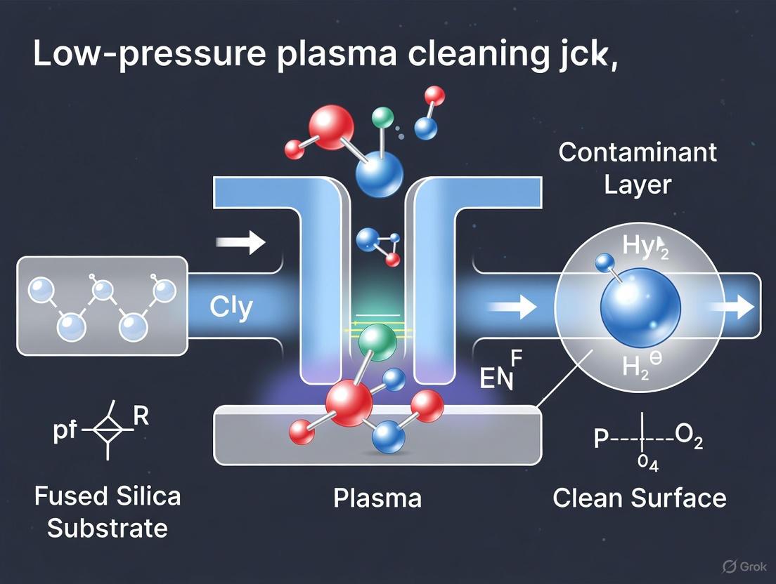
The core mechanism involves the ionization of a working gas, such as oxygen or argon, via low-pressure radio-frequency (RF) capacitive coupling discharge. This process generates a large-area, uniform, diffuse plasma. The reactive species within this plasma, including radicals, ions, and electrons, then interact with the organic contaminants [1] [9]. The primary removal process is chemical decomposition driven by reactive oxygen species (ROS), which can be significantly enhanced by the kinetic energy of plasma particles. This kinetically assisted chemical removal leads to the stepwise decomposition of organic molecules into small, volatile molecular groups that desorb from the surface [16].
Key Radical Reaction Pathways and Quantitative Analysis
Dominant Reaction Pathways
Reactive molecular dynamics (ReaxFF MD) simulations have been instrumental in elucidating the atomic-scale reaction mechanisms. Using dibutyl phthalate (DBP) as a representative model pollutant, two dominant radical-driven reaction pathways have been identified [16]:
- Butyl Chain Cleavage: Radicals, particularly atomic oxygen, attack the alkoxy groups of the molecule, leading to the scission of C-O bonds and the subsequent breakdown of the carbon chains.
- Benzene Ring Cleavage: Energetic radicals open and fragment the aromatic ring structure, ultimately leading to the complete mineralization of the molecule.
The following diagram illustrates the sequential nature of these radical-driven pathways for a model organic contaminant.
Quantitative Efficacy of Kinetic Enhancement
While the core mechanism is chemical, the initial kinetic energy of the reactive oxygen species is a critical promoter. It enhances the transport and penetration of radicals into the contaminant layer and facilitates energy transfer to overcome reaction energy barriers [16]. The following table summarizes the quantitative enhancement of contaminant decomposition due to the kinetic energy of plasma species, as revealed by ReaxFF MD simulations.
Table 1: Quantitative Effect of Kinetic Energy on Contaminant Decomposition (ReaxFF MD Data)
| Initial Kinetic Energy of ROS | DBP Residue Ratio | Enhancement of Decomposition Rate | Key Activated Pathways |
|---|---|---|---|
| 0.0083 eV | High | Baseline (1x) | Limited thermal reactions |
| 75 eV | Low | Up to 1310% increase | C-O cleavage, C-C fission, ring opening |
Experimental Protocol for Plasma Cleaning of Fused Silica Optics
Research Reagent Solutions and Essential Materials
The following table lists the key materials, reagents, and equipment required for the experimental investigation of low-pressure plasma cleaning of optical components.
Table 2: Essential Research Reagents and Materials for Plasma Cleaning Studies
| Item Name | Function/Description | Application Context |
|---|---|---|
| Fused Silica Substrates | Optical component material; can be uncoated, or with sol-gel SiO₂ chemical coatings [1] [17]. | Primary sample for cleaning efficacy and damage studies. |
| Dibutyl Phthalate (DBP) | Representative model organic contaminant [16]. | Used in simulation and experimental studies to standardize contamination. |
| Oxygen (O₂) Gas | Primary process gas; source of reactive oxygen species (O, O₂⁺) [1] [16]. | Drives chemical decomposition of organic contaminants. |
| Argon (Ar) Gas | Inert process gas; can be used for physical sputtering or in gas mixtures [1]. | Used to study physical bombardment effects. |
| Low-Pressure RF Plasma System | Capacitively coupled plasma reactor with vacuum pump, gas flow control, and RF power generator (e.g., 13.56 MHz) [1]. | Core apparatus for generating non-equilibrium plasma. |
| Langmuir Probe | Diagnostic tool for measuring plasma parameters (plasma potential, ion density, electron temperature) [1]. | Characterizing plasma discharge properties. |
| Emission Spectrometer | Diagnostic tool for identifying types of reactive particles excited in the plasma [1]. | Monitoring active radical species in real-time. |
Step-by-Step Workflow for Plasma Cleaning and Analysis
The following diagram outlines the integrated experimental and simulation workflow for developing and optimizing a plasma cleaning process.
Protocol Steps:
Sample Preparation:
- Prepare chemical-coated fused silica samples using a dip-coating method with a sol-gel SiO₂ solution designed for 355 nm laser applications [1].
- Contaminate samples with a representative organic contaminant (e.g., a calibrated amount of DBP or exposure to vacuum outgassing compounds) to create a standardized test surface [16] [17].
Plasma System Setup & Parameterization:
In-situ Plasma Diagnostics (Optional but Recommended):
- Use a Langmuir probe to measure fundamental plasma parameters such as plasma potential, ion density, and electron temperature. This establishes a quantitative relationship between input power and the resulting plasma characteristics [1].
- Employ Optical Emission Spectroscopy (OES) to identify the specific reactive oxygen species (e.g., atomic oxygen radicals) present in the plasma, confirming the activation of radical-driven pathways [1].
Ex-situ Surface and Performance Analysis:
- Water Contact Angle: Measure the contact angle before and after cleaning. A significant decrease indicates the removal of hydrophobic organic contaminants and increased surface hydrophilicity [17].
- Atomic Force Microscopy (AFM): Image the surface topography to directly assess the removal of contaminants and, critically, to check for any nano-scale roughening or pit formation due to over-cleaning [14] [17].
- X-ray Photoelectron Spectroscopy (XPS): Analyze the surface chemical composition to confirm the reduction of carbon content and the chemical state of the fused silica surface post-cleaning [1].
- Optical Transmittance: Measure the transmittance of the optic at the target wavelength (e.g., 355 nm). Successful cleaning should restore transmittance to near-baseline levels [1] [17].
- Laser-Induced Damage Threshold (LIDT): Test the LIDT to ensure that the cleaning process not only restores optical performance but also maintains or improves the component's resistance to laser damage [17].
Critical Considerations for Non-Destructive Cleaning
A paramount concern in plasma cleaning is avoiding damage to the fused silica substrate. Molecular dynamics simulations reveal that once organic contaminants are fully removed, continued plasma irradiation (over-cleaning) leads to the formation of nano-defects [14].
- Damage Mechanism: Oxygen plasma bombardment disrupts Si-O bonds in the fused silica lattice, leading to the sputtering of silicon and oxygen atoms and the formation of pit defects. Significant surface damage is observed when the energy of bombarding species exceeds a critical threshold (e.g., ~33 eV) [14].
- Process Window Optimization: The cleaning process must operate within a window defined by minimum cleaning time (for complete contaminant removal) and maximum cleaning time (before onset of substrate damage). Parameters like discharge power and process gas pressure directly influence the aggressiveness of the plasma and must be carefully tuned to this window [1] [14].
This application note establishes that the removal of organic contaminants from fused silica optics via low-pressure plasma is predominantly governed by radical-driven chemical reactions, with physical kinetic energy acting as a crucial enhancer. The integration of experimental diagnostics with ReaxFF molecular dynamics simulations provides a powerful methodology to decode the atomic-scale pathways and optimize process parameters. By adhering to the detailed protocols and recognizing the critical balance between cleaning efficacy and substrate preservation, researchers can implement a robust, non-destructive cleaning strategy. This ensures the longevity and performance stability of high-value optical components in intense laser systems.
Molecular Dynamics Simulations of Plasma-Surface Interactions
Application Note: Nano-Defect Formation on Fused Silica Optics
Low-pressure plasma cleaning has emerged as a critical technology for maintaining the ultra-high cleanliness requirements of fused silica optics in precision laser systems, particularly within vacuum environments [8]. While effectively removing organic contaminants, prolonged plasma exposure can induce nanoscale damage on the optically active surfaces, ultimately degrading performance [8]. This application note examines the atomic-scale mechanisms of plasma-induced nano-defect formation on fused silica surfaces using Molecular Dynamics (MD) simulations. The insights gained are foundational for developing non-destructive cleaning protocols within the broader context of fused silica optics preservation.
Quantitative Damage Parameters from MD Simulations
MD simulations reveal critical parameters and thresholds governing surface damage during oxygen plasma irradiation of fused silica. The tables below summarize key quantitative findings.
Table 1: Plasma Energy Parameters and Damage Effects
| Plasma Energy (eV) | Observed Effect on Fused Silica Surface |
|---|---|
| ~3 (Electron Temperature) | Typical electron temperature in RF plasma; sheath voltage can reach hundreds of volts [8]. |
| <33 eV | Region below significant damage threshold [8]. |
| >33 eV | Onset of significant surface damage; bond disruption and atomic sputtering occur [8]. |
| 74 eV (Case Study) | Observable pit defect formation and successive sputtering of silicon-oxygen atoms [8]. |
Table 2: Temporal Evolution of Surface Damage
| Irradiation Time | Damage Depth | Atomic Sputtering Observation |
|---|---|---|
| Initial 10 ps | Damage initiates | Linear increase in sputtered atoms; Si:O sputtering ratio ~ 1.5:1 [8]. |
| 100 ps | ~17.03 Å | Damage depth reaches a plateau despite continued irradiation [8]. |
| Post-irradiation | Morphology stable | Sputtered atoms aggregate into molecular clusters in the vacuum [8]. |
Key Findings and Mechanisms
The interaction between oxygen plasma and fused silica is characterized by two primary mechanisms:
- Physical Sputtering: Energetic ions (e.g., Ar⁺) accelerated from the plasma bombard the surface, transferring kinetic energy to lattice atoms. When this energy exceeds the surface binding energy, atoms are physically ejected [18].
- Chemical Reaction & Bond Disruption: Reactive species, particularly oxygen radicals, disrupt the Si-O network bonds of fused silica. This leads to the successive sputtering of silicon and oxygen atoms [8].
Simulations show that temperature is a crucial factor affecting the extent of surface damage [8]. Furthermore, neutral oxygen atoms play a key role in forming distinctive pit defects and interface damage patterns [8]. After the initial damage layer forms, subsequent oxygen ions can bombard previously deposited ions, creating a protective layer that causes the damage depth to plateau over time [8].
Protocol: Molecular Dynamics Simulation of Plasma-Surface Interaction
Simulation Setup and Workflow
This protocol details the procedure for establishing and running an MD simulation to investigate low-temperature oxygen plasma interactions with a fused silica surface.
Table 3: Research Reagent Solutions and Computational Materials
| Item Name | Function/Description |
|---|---|
| Fused Silica Substrate | Amorphous SiO₂ structure representing the optical component surface [8]. |
| Oxygen Plasma Species | Source of neutral oxygen atoms (O) and ions (O⁺) for bombardment [8]. |
| ReaxFF Force Field | A reactive force field used to describe bond breaking and formation during plasma-surface interactions [8] [1]. |
| LAMMPS / Similar MD Engine | Software to perform the molecular dynamics calculations. |
| Visualization Software (e.g., OVITO) | For analyzing simulation trajectories, defect identification, and rendering atomic configurations. |
Figure 1: MD Simulation Workflow for Plasma-Surface Interaction.
Step-by-Step Procedure
Model Construction
- Build an atomic model of a fused silica substrate. The model should be large enough to minimize periodic boundary effects and have a defined surface plane.
- Create a simulation box that includes a vacuum region above the substrate surface to accommodate plasma species and sputtered atoms [8].
Force Field Selection and Validation
- Employ a reactive force field (ReaxFF) parameterized for Si/O systems. This force field is critical as it allows for dynamic bond breaking and formation during the simulation [8] [1].
- Ensure the force field can accurately reproduce the bonding structure and known material properties of fused silica.
System Equilibration
- Perform energy minimization of the initial structure to remove any unrealistic atomic clashes.
- Equilibrate the fused silica substrate at the target temperature (e.g., 300 K) using an NVT (constant Number, Volume, and Temperature) ensemble for a sufficient duration (e.g., tens of picoseconds) to stabilize the system.
Plasma Bombardment Phase
- Introduce plasma particles (e.g., neutral oxygen atoms) one by one or in small groups toward the substrate surface.
- Set the kinetic energy of the incident particles based on the parameter under investigation (e.g., 33 eV, 74 eV). The direction can be perpendicular or follow a defined distribution [8].
- The flux is controlled by the time interval between particle injections. A typical simulation might involve 10-100 ps of continuous plasma irradiation [8].
- Use an NVE (constant Number, Volume, and Energy) ensemble during this bombardment phase to correctly model energy transfer.
Post-Irradiation Relaxation
- After ceasing plasma particle injection, allow the system to relax for a further period (e.g., 90 ps) under NVT conditions. This allows the system to reach a new stable state and for sputtered atoms to form clusters [8].
Data Collection and Analysis
- Trajectory Output: Save atomic coordinates and velocities at regular intervals for post-processing.
- Sputtering Yield: Count the number of silicon and oxygen atoms that are permanently ejected from the substrate surface. Track the O:Si ratio of sputtered atoms [8].
- Damage Depth Analysis: Calculate the erosion depth of the original surface over time. Monitor the injection depth of oxygen atoms into the substrate [8].
- Defect Identification: Use coordination number analysis to identify under-coordinated atoms and visualize pit formation or surface roughening.
Critical Parameters for Experimental Correlation
For MD simulations to effectively guide macroscopic experiments, specific parameters must be aligned.
Figure 2: Correlation Framework Between Simulation and Experiment.
- Particle Energy: The kinetic energy of ions/atoms in the simulation (e.g., 33 eV, 74 eV) must correspond to the plasma sheath potential in experimental RF plasmas, which can reach hundreds of volts [8].
- Particle Flux: The rate of particle injection in the simulation should be calibrated, where possible, to the ion flux density measured experimentally via Langmuir probes [1].
- Temperature Control: The substrate temperature in the simulation is a direct input and a crucial factor affecting surface damage, which must be controlled and matched to experimental conditions [8].
Spatial Distribution of Plasma Discharge Characteristics in Capacitive-Coupling Systems
In the field of low-pressure plasma cleaning for fused silica optics, mastering the spatial distribution of plasma discharge characteristics is paramount for achieving uniform and efficient removal of organic contaminants. Capacitively coupled plasma (CCP) systems, typically energized by radio-frequency (RF) power sources, are widely employed for this purpose due to their ability to generate large-area, uniform plasma under low-pressure conditions [1] [19]. The control of this spatial uniformity is critical, as non-uniform plasma distributions can lead to uneven cleaning of large-aperture optical components, directly compromising their laser damage threshold and overall optical performance [1]. This application note provides a detailed experimental framework for characterizing and optimizing the spatial distribution of plasma discharge parameters, enabling researchers to achieve reproducible and effective cleaning of fused silica optics.
Key Plasma Parameters and Their Spatial Relationship
The spatial distribution of capacitively coupled plasma is governed by several interdependent parameters. Understanding these relationships is essential for experimental design and interpretation.
Table 1: Key Plasma Parameters and Their Interdependencies in Capacitive-Coupling Systems
| Parameter | Spatial Influence | Effect on Plasma Uniformity | Typical Measurement Technique |
|---|---|---|---|
| Excitation Frequency | Determines electromagnetic wavelength on electrodes; affects standing wave formation [20]. | Higher frequencies (e.g., 150 MHz) promote significant standing wave effects and voltage non-uniformity compared to 13.56 MHz [20]. | Impedance analyzer, Network analyzer |
| Discharge Power | Influences electron temperature, ion density, and plasma potential [1]. | Optimal power range ensures stable discharge without constriction; affects density profile [1]. | Langmuir probe, IV probe |
| Gas Pressure | Affects mean free path and ionization collision rate [1]. | Lower pressures often improve uniformity but require optimal power coupling [1]. | Capacitance manometer, Barometer |
| Electrode Geometry & Size | Larger electrodes (relative to wavelength) exacerbate standing wave effects [20]. | Center-to-edge voltage variations occur; 1m electrode at 150 MHz shows >50% voltage variation [20]. | Caliper, Design specifications |
| Plasma Impedance (Zp) | Nonlinear characteristic; varies with applied power and geometry [20]. | Uniformity is achieved when impedance is constant across the electrode area [20]. | Langmuir probe, IV waveform analysis |
Experimental Protocols for Spatial Distribution Analysis
Langmuir Probe Characterization of Plasma Parameters
Objective: To measure the spatial variations of plasma potential, ion density, and electron temperature across the electrode area.
Materials:
- Low-pressure capacitive-coupled plasma reactor with RF source (typically 13.56 MHz or higher)
- Langmuir probe system with positioning mechanism
- Data acquisition system
- Vacuum pump system and pressure gauge
- High-precision XYZ probe manipulator
- Process gases (Ar, O₂)
Procedure:
- System Setup: Establish a stable low-pressure plasma discharge using Ar or O₂ as the working gas. Maintain constant pressure (e.g., 10-100 mTorr) and gas flow rate.
- Probe Calibration: Calibrate the Langmuir probe using a standard plasma source prior to measurements.
- Spatial Mapping: Program the XYZ manipulator to move the probe to predetermined positions across the plasma region, particularly between the electrodes.
- Data Collection: At each position, obtain current-voltage (I-V) characteristics by sweeping the probe voltage.
- Parameter Extraction: Analyze the I-V characteristics to derive local plasma potential, ion density, and electron temperature using appropriate theory (e.g., Orbital Motion Limited theory).
- Data Visualization: Create 2D contour maps of each parameter to visualize spatial distribution.
Note: The probe should be carefully cleaned before and after experiments to avoid contamination of measurements.
Voltage Distribution Mapping via Transmission Line Modeling (TLM)
Objective: To computationally determine the voltage distribution across large-area electrodes, identifying standing wave effects.
Materials:
- Computational electromagnetics software (e.g., COMSOL Multiphysics, SEMCAD)
- Electrode material properties (conductivity, magnetic permeability)
- Experimentally measured plasma impedance data
Procedure:
- Model Construction: Create a finite element model of the electrode system, including upper electrode, lower grounded electrode, and plasma region.
- Parameter Definition:
- Simulation Setup: Apply RF excitation at specified frequency (e.g., 13.56 MHz or 150 MHz) at chosen power application point(s).
- Boundary Conditions: Set electrode edges as open-circuit or capacitive termination based on actual reactor design.
- Solution: Solve the 2D wave equation using the finite difference method to compute voltage amplitude at each node across the electrode surface.
- Analysis: Identify regions of maximum and minimum voltage amplitude, quantifying center-to-edge variation.
Table 2: Exemplary Voltage Distribution Data for 1m Electrode (Relative to Center Voltage)
| Position from Center (m) | 13.56 MHz Excitation | 150 MHz Excitation |
|---|---|---|
| 0.0 | 1.00 | 1.00 |
| 0.1 | 0.99 | 0.95 |
| 0.2 | 0.98 | 0.82 |
| 0.3 | 0.96 | 0.65 |
| 0.4 | 0.93 | 0.48 |
| 0.5 | 0.90 | 0.35 |
Data adapted from calculations showing standing wave effect severity increases with frequency [20].
Optical Emission Spectroscopy (OES) for Reactive Species Distribution
Objective: To map the spatial distribution of key reactive species (e.g., oxygen radicals) responsible for organic contaminant removal.
Materials:
- Spectrometer with optical fiber
- XYZ positioning system for fiber optic collector
- Calibrated light source for wavelength intensity calibration
Procedure:
- Plasma Ignition: Generate oxygen-based plasma at specified operating conditions.
- Spectral Acquisition: Position the optical fiber at various locations in the plasma chamber and collect emission spectra.
- Species Identification: Identify characteristic emission lines for key species (e.g., atomic oxygen at 777 nm).
- Intensity Mapping: Create spatial maps of emission intensity for each species, proportional to their concentration.
- Correlation: Correlate species distribution with cleaning efficacy measured via transmittance recovery of contaminated optics.
Visualization of Experimental Workflow and Plasma-Surface Interactions
The Scientist's Toolkit: Essential Research Reagents and Materials
Table 3: Essential Materials and Reagents for Plasma Discharge Studies
| Item | Function/Application | Specification Notes |
|---|---|---|
| Fused Silica Substrates | Sample material for contamination and cleaning studies | High-purity, often with sol-gel SiO₂ chemical coatings at 355 nm wavelength [1] |
| Process Gases (Ar, O₂) | Plasma generation and reactive species production | High-purity grade (99.99%+); O₂ enables radical-driven organic contaminant removal [1] |
| Langmuir Probe System | Spatial measurement of plasma parameters (potential, density, temperature) | Requires precise positioning system and appropriate data acquisition software [1] |
| RF Power Supply & Matching Network | Plasma generation and impedance matching | Typically 13.56 MHz industrial standard; matching network minimizes reflected power [1] [19] |
| Optical Emission Spectrometer | Identification and spatial mapping of reactive species | Wavelength range 200-800 nm; fiber optic coupling for spatial scanning [1] |
| Vacuum System | Maintaining low-pressure environment for plasma | Base pressure ~10⁻⁶ Torr; pressure control during gas flow [1] |
| Contamination Sources | Simulating real-world organic contamination on optics | Controlled deposition of hydrocarbon-based contaminants [1] |
Achieving uniform spatial distribution of plasma discharge characteristics is fundamental to the success of low-pressure plasma cleaning processes for fused silica optics. The experimental protocols detailed in this application note—encompassing Langmuir probe diagnostics, transmission line modeling of voltage distribution, and optical emission spectroscopy—provide researchers with a comprehensive methodology for characterizing and optimizing capacitive-coupled plasma systems. The correlation between these plasma parameters and cleaning effectiveness, particularly the restoration of optical transmittance and laser damage threshold, enables the development of highly efficient, reproducible cleaning processes essential for maintaining the performance of high-power laser systems.
Implementing Plasma Cleaning: Process Parameters and Practical Applications
RF Capacitive-Coupling Discharge Systems for Optical Component Cleaning
In intense laser systems, such as those used in inertial confinement fusion and fundamental scientific research, the performance and longevity of large-aperture optical components are critically limited by organic contamination. During prolonged operation in vacuum environments, these surfaces inevitably accumulate hydrocarbon-based contaminants. Under intense laser irradiation, these contaminants ablate or decompose, generating stray light that damages delicate chemical coatings and reduces the laser-induced damage threshold (LIDT) of optical components by approximately 60% [1]. This degradation severely limits the operational efficiency and output capability of the entire laser facility.
Low-pressure plasma cleaning technology, specifically utilizing Radio-Frequency (RF) capacitive-coupling discharge, has emerged as a superior solution for addressing this challenge. This technology efficiently generates a large-area, uniform, diffuse plasma that can remove organic contaminants without causing secondary contamination or damage to sensitive optical coatings. Unlike wet cleaning methods or other dry cleaning techniques, RF plasma cleaning can be performed in situ without disassembling precision optical components, making it particularly valuable for large-aperture optics in complex laser systems [1] [21].
This document provides detailed application notes and experimental protocols for implementing RF capacitive-coupling discharge systems, specifically framed within research on low-pressure plasma cleaning of fused silica optics.
Fundamental Principles
Plasma Generation via RF Capacitive Coupling
In RF capacitive-coupling discharge systems, electrical energy is transferred to a low-pressure gas through capacitive coupling at radio frequencies (typically in the kHz to MHz range). This energy transfer ionizes the gas molecules, creating a plasma containing reactive species including ions, electrons, radicals, and excited molecules [1].
The capacitive coupling mechanism involves two parallel electrodes forming a capacitor, with the optical component and processing chamber acting as the dielectric medium. When RF power is applied, oscillating electric fields accelerate free electrons, which then collide with neutral gas molecules, initiating and sustaining the plasma through ionization processes.
Contaminant Removal Mechanisms
The removal of organic contaminants occurs through two primary mechanisms:
- Chemical Reaction: Reactive species in the plasma (particularly oxygen radicals in an oxygen-based plasma) react with hydrocarbon contaminants, breaking them down into volatile compounds (e.g., CO₂, H₂O) that are evacuated by the vacuum system [1].
- Physical Sputtering: Energetic ions from the plasma bombard the surface, physically dislodging contaminant molecules through momentum transfer. The randomly directed ion bombardment under relatively low pressure and temperature conditions enables efficient yet non-destructive cleaning [1].
Reactive molecular dynamics simulations have revealed that these processes occur on nanosecond timescales at atomic spatial scales, involving complex reaction pathways between plasma species and organic contaminants [1].
Experimental Protocols
System Configuration and Setup
Essential Components
The experimental setup for low-pressure plasma cleaning requires the following core subsystems:
- Vacuum Chamber: Constructed of stainless steel with appropriate electrical feedthroughs and viewports.
- RF Power Supply and Matching Network: Typically operating at 13.56 MHz industry standard frequency with impedance matching to maximize power transfer.
- Capacitive Electrodes: Parallel plates within the vacuum chamber, often with the sample placed on the grounded electrode.
- Vacuum System: Comprising roughing and turbo-molecular pumps to achieve base pressure of 10⁻² to 10⁻³ mbar.
- Gas Delivery System: Mass flow controllers for precise regulation of process gases (oxygen, argon, or mixtures).
- Diagnostic Instruments: Langmuir probe, optical emission spectrometer, and process monitors.
Sample Preparation Protocol
- Substrate Cleaning: Begin with fused silica substrates cleaned using standard solvent procedures (isopropanol followed by acetone in ultrasonic bath).
- Chemical Coating Application: Apply sol-gel SiO₂ chemical coatings using dip-coating methodology:
- Submerge three-quarters of the substrate height in coating sol for 2 minutes to ensure full contact.
- Withdraw at constant speed of 85 mm/min using precision pull-coating apparatus [1].
- Perform post-treatment with ammonia and hexamethyldisilazane (HMDS) in sealed container for 24 hours to enhance coating stability [1].
- Contamination Procedure: Artificially contaminate samples in controlled vacuum environment to simulate operational conditions of intense laser systems.
Plasma Characterization Methods
Langmuir Probe Analysis
Objective: To determine fundamental plasma parameters including plasma potential, ion density, and electron temperature under varying discharge conditions.
Procedure:
- Insert Langmuir probe into plasma discharge region at predetermined positions.
- Sweep probe voltage from negative to positive bias relative to ground while measuring current.
- Record current-voltage (I-V) characteristics at multiple locations within the plasma.
- Analyze I-V curves using appropriate theory to extract:
- Electron temperature from the exponential region of the electron retardation current
- Ion density from the ion saturation current region
- Plasma potential from the point where the second derivative of the I-V curve is zero
- Repeat measurements across variations in discharge power (50-300 W) and gas pressure (0.1-1.0 mbar).
Optical Emission Spectroscopy
Objective: To identify reactive species present in the plasma and correlate their presence with cleaning effectiveness.
Procedure:
- Couple optical fiber to viewport on vacuum chamber with direct line-of-sight to plasma region.
- Connect fiber to spectrometer with appropriate wavelength range (200-800 nm).
- Acquire emission spectra with integration times sufficient for adequate signal-to-noise.
- Identify characteristic emission lines for:
- Oxygen plasma: Atomic oxygen (777 nm, 844 nm), O₂⁺ bands, excited molecular states
- Argon plasma: Ar I lines (750 nm, 811 nm)
- Correlate emission intensities with process parameters and cleaning performance.
Cleaning Effectiveness Evaluation
Surface Cleanliness Assessment
Water Contact Angle Measurements:
- Place cleaned optical component on level stage of contact angle goniometer.
- Dispense 2-5 µL deionized water droplet onto surface using precision syringe.
- Capture image of droplet profile immediately after deposition.
- Measure contact angle using sessile drop method.
- Compare pre-cleaning and post-cleaning values, with lower angles indicating higher cleanliness and hydrophilicity [21].
Atomic Force Microscopy (AFM):
- Mount sample on AFM specimen stage.
- Scan surface areas of 5×5 µm to 20×20 µm using tapping mode.
- Acquire height and phase images with resolution sufficient to resolve nanoscale features.
- Calculate surface roughness parameters (Ra, Rq) from height data.
- Compare topography before and after cleaning to verify contaminant removal without damage to chemical coatings [21].
Optical Performance Metrics
Transmittance Measurements:
- Place sample in UV-Vis spectrophotometer with appropriate beam diameter.
- Measure transmittance across wavelength range 300-800 nm, with particular attention to operational wavelength (e.g., 355 nm for intense laser systems).
- Compare to baseline measurements of uncontaminated samples.
- Establish quantitative relationship between number of organic functional groups and transmittance values [1].
Laser-Induced Damage Threshold (LIDT) Testing:
- Place sample in controlled test chamber with capability for in situ damage monitoring.
- Irradiate multiple sites with laser pulses at varying fluence levels (R-on-1 or S-on-1 methodology).
- Monitor for damage events using scattered light detection or online microscopy.
- Calculate damage probability curve and extract LIDT value (typically at 0% damage probability).
- Compare LIDT before and after cleaning to quantify performance recovery [21].
Quantitative Data and Process Optimization
Plasma Parameters Under Varied Conditions
Table 1: Plasma characteristics as function of discharge power and pressure in oxygen-based RF capacitive discharge
| Discharge Power (W) | Gas Pressure (mbar) | Plasma Potential (V) | Ion Density (cm⁻³) | Electron Temperature (eV) |
|---|---|---|---|---|
| 50 | 0.2 | 18.5 | 8.7×10⁹ | 3.2 |
| 100 | 0.2 | 22.1 | 1.5×10¹⁰ | 2.9 |
| 150 | 0.2 | 25.8 | 2.3×10¹⁰ | 2.7 |
| 200 | 0.2 | 28.3 | 3.1×10¹⁰ | 2.5 |
| 100 | 0.1 | 24.5 | 9.8×10⁹ | 3.3 |
| 100 | 0.3 | 20.2 | 1.8×10¹⁰ | 2.6 |
| 100 | 0.5 | 18.7 | 2.1×10¹⁰ | 2.3 |
Cleaning Performance Metrics
Table 2: Optical component performance recovery after low-pressure plasma cleaning
| Sample Condition | Water Contact Angle (°) | Transmittance at 355 nm (%) | LIDT (J/cm²) | Surface Roughness Ra (nm) |
|---|---|---|---|---|
| Uncontaminated Baseline | 25 | 99.8 | 25 | 0.55 |
| Contaminated | 82 | 95.3 | 10 | 1.09 |
| After Plasma Cleaning | 28 | 99.5 | 24 | 0.58 |
| Percentage Recovery | 96% | 99.7% | 96% | 95% |
Research Reagent Solutions
Table 3: Essential materials and reagents for plasma cleaning research
| Material/Reagent | Function/Application | Specifications/Notes |
|---|---|---|
| Sol-gel SiO₂ Coating Sol | Application of chemical coatings on fused silica substrates | Particle size 29 nm; optimized for 355 nm wavelength [1] |
| Hexamethyldisilazane (HMDS) | Post-treatment of chemical coatings to enhance stability | Used in vapor phase treatment for 24 hours in sealed container [1] |
| High-Purity Oxygen (O₂) | Primary process gas for organic contaminant removal | Generates oxygen radicals for chemical breakdown of hydrocarbons [1] |
| High-Purity Argon (Ar) | Process gas for physical sputtering or as carrier gas in mixtures | Enables ion bombardment mechanism; sometimes mixed with oxygen [1] |
| Fused Silica Substrates | Base material for optical components in intense laser systems | High LIDT requirement; various sizes including large-aperture formats [21] |
| Dip-Coating Apparatus | Application of uniform chemical coatings on substrate surfaces | Constant pull speed of 85 mm/min; precision immersion mechanism [1] |
Visualization of Processes and Workflows
Experimental Workflow for Plasma Cleaning Research
Plasma-Contaminant Interaction Mechanisms
RF capacitive-coupling discharge systems provide an effective, controllable, and non-destructive method for removing organic contaminants from precision optical components used in intense laser systems. The technology successfully restores the optical performance of contaminated components, with demonstrated recovery of approximately 99.7% of original transmittance and 96% of laser-induced damage threshold [21].
The optimal cleaning efficiency is achieved through careful control of discharge parameters, particularly power and pressure, which directly influence the plasma characteristics and consequent cleaning mechanisms. The combination of experimental diagnostics with molecular dynamics simulations provides comprehensive insights into the fundamental processes occurring at the atomic scale during plasma cleaning [1].
For researchers pursuing advanced studies in this field, future work should focus on refining process parameters for specific coating types, investigating long-term effects of repeated cleaning cycles, and developing real-time monitoring techniques for process control. The integration of these advanced plasma cleaning protocols will contribute significantly to enhancing the performance and longevity of optical systems in demanding scientific and industrial applications.
Within the broader research on low-pressure plasma cleaning of fused silica optics, the precise optimization of core process parameters is critical for achieving effective contaminant removal while preserving the optical substrate's integrity. Discharge power, gas pressure, and treatment duration form a interconnected set of variables that directly control the plasma's physical and chemical properties, thereby dictating both cleaning efficiency and potential surface damage [1] [8]. This document provides detailed application notes and experimental protocols to guide researchers in systematically optimizing these parameters, framed within the context of advancing non-destructive, high-performance cleaning techniques for intense laser systems and other high-precision optical applications [21].
Parameter Effects and Quantitative Relationships
The core parameters influence the plasma cleaning process through distinct yet interconnected mechanisms. The following table summarizes the quantitative and qualitative effects of varying these key parameters, synthesizing findings from experimental and simulation studies [1] [22] [8].
Table 1: Effects of Core Plasma Cleaning Parameters on Process Outcomes
| Parameter | Key Effects and Quantitative Relationships |
|---|---|
| Discharge Power | - Ion Density: Increases linearly with rising RF power, enhancing the flux of reactive species [1].- Cleaning Rate: Positively correlated with power, but requires optimization to balance efficiency against the risk of surface damage from high-energy ion bombardment [1] [8].- Electron Temperature: Moderately increases with power, affecting the excitation of reactive species [1]. |
| Gas Pressure | - Plasma Uniformity: Lower pressures (e.g., in the medium-pressure range of 11.6 mbar) promote diffuse, uniform plasmas, which are crucial for uniform cleaning of large apertures [22].- Ion Energy vs. Flux: Lower pressure increases mean free path, leading to higher ion bombardment energy, while higher pressure increases radical density and chemical etching contribution [1] [8].- Process Window: A medium-pressure regime can balance chemical vaporization and minimize damaging physical ion sputtering [22]. |
| Treatment Duration | - Contaminant Removal: Cleaning effectiveness increases with time until organic layers are fully removed [21].- Over-cleaning Risk: Prolonged exposure after contaminant removal leads to nano-defect formation on the fused silica substrate, degrading optical performance. The damage depth increases with time before plateauing [8].- Linear Sputtering: Molecular dynamics simulations show the quantity of sputtered Si atoms has a linear correlation with irradiation time [8]. |
Experimental Protocols for Parameter Optimization
This section outlines detailed methodologies for conducting experiments to establish the optimal windows for discharge power, gas pressure, and treatment duration.
Protocol: Systematic Evaluation of Discharge Power and Gas Pressure
Objective: To determine the combined effect of discharge power and gas pressure on plasma characteristics and cleaning efficacy.
Materials:
- Low-pressure plasma reactor with RF source (e.g., 13.56 MHz or 40.68 MHz)
- Langmuir probe system
- Optical Emission Spectrometer (OES)
- Fused silica samples with standardized organic contamination
- Goniometer for water contact angle measurements
- Spectrophotometer for transmittance measurements
- Atomic Force Microscope (AFM)
Procedure:
- Sample Preparation: Prepare contaminated fused silica samples using a dip-coating method with a consistent pull-speed (e.g., 85 mm/min) to ensure uniform contaminant layers [1].
- Parameter Matrix: Design a experiment varying RF power (e.g., 50 W to 150 W) and gas pressure (e.g., 5 to 20 mbar) while using a fixed, standard gas mixture (e.g., O₂ and Ar) and an initial treatment duration.
- Plasma Characterization: For each parameter set:
- Cleaning Efficacy Assessment: After processing:
- Measure the water contact angle to characterize surface energy and cleanliness [21].
- Quantify optical transmittance at the target wavelength (e.g., 355 nm) to assess performance recovery [1] [21].
- Use AFM to scan the surface and quantify the removal of contaminants and any change in surface roughness [21].
- Data Analysis: Construct contour plots or response surfaces to visualize the relationship between power, pressure, and the measured responses (e.g., ion density, transmittance recovery).
Protocol: Establishing Treatment Duration and Damage Threshold
Objective: To identify the optimal treatment time that ensures complete contaminant removal while avoiding substrate damage.
Materials:
- Low-pressure plasma reactor
- Fused silica samples with standardized organic contamination
- Laser-Induced Damage Threshold (LIDT) test setup
- X-ray Photoelectron Spectrometer (XPS) or Raman Spectrometer
- Molecular Dynamics (MD) simulation software (e.g., LAMMPS with ReaxFF force field)
Procedure:
- Experimental Duration Sweep: Process contaminated samples for a series of durations (e.g., from 1 to 30 minutes) at a fixed, optimized power and pressure.
- Post-Process Analysis:
- Use XPS or Raman spectroscopy to monitor the disappearance of carbon signatures (indicating organic removal) and the subsequent emergence of surface network defects on the fused silica itself [8] [23].
- Test the LIDT of the cleaned samples to correlate cleaning duration with the recovery and potential degradation of optical performance [21].
- Molecular Dynamics Simulation:
- Construct an atomistic model of the fused silica surface with an adsorbed hydrocarbon contaminant layer.
- Simulate the bombardment of oxygen plasma at varying energies (e.g., 10 eV to 100 eV) and fluxes, tracking the removal of contaminant atoms and the sputtering of substrate Si and O atoms [1] [8].
- Identify the critical energy threshold (e.g., ~33 eV [8]) where significant substrate damage initiates.
- Correlate simulated sputtering yields and damage depths with experimental results to validate the model.
The Scientist's Toolkit: Essential Research Reagents and Materials
Table 2: Key Reagents and Materials for Plasma Cleaning Research
| Item | Function/Application |
|---|---|
| Fused Silica Substrates | The primary optical material under study, serving as the substrate for chemical coatings and the recipient of plasma cleaning [1] [21]. |
| Sol-Gel SiO₂ Coating | A chemical coating applied to fused silica to create anti-reflective or other functional surfaces, representing a sensitive layer that must be preserved during cleaning [1]. |
| Oxygen (O₂) Gas | The most common reactive gas for plasma cleaning; it generates oxygen radicals that chemically react with and volatilize organic contaminants [1] [8]. |
| Argon (Ar) Gas | Often used as a carrier or auxiliary gas; Ar plasma can provide physical sputtering, and it helps in sustaining a stable plasma discharge [1]. |
| Hexamethyldisilazane (HMDS) | Used in the post-treatment of sol-gel coatings to modify surface chemistry and enhance stability [1]. |
| ReaxFF Force Field | A reactive force field for molecular dynamics simulations, enabling atomic-scale modeling of the chemical reactions between plasma species and the substrate/contaminant [1] [8]. |
Workflow and Decision Pathways for Parameter Optimization
The following diagram illustrates the integrated experimental and simulation workflow for optimizing plasma cleaning parameters, ensuring a systematic approach from hypothesis to validation.
Figure 1: Integrated workflow for parameter optimization, combining macro-experiments and micro-simulations.
The non-destructive plasma cleaning of high-value fused silica optics is critically dependent on the balanced optimization of discharge power, gas pressure, and treatment duration. The protocols outlined herein provide a roadmap for researchers to navigate this complex parameter space. By integrating macroscopic experimental diagnostics with atomic-scale molecular dynamics simulations, it is possible to not only determine effective cleaning recipes but also to understand the fundamental mechanisms behind contamination removal and substrate damage [1] [8]. This dual approach ensures the development of robust, reliable plasma cleaning processes that restore the optical performance of components while safeguarding their long-term durability in demanding applications.
In the context of low-pressure plasma cleaning of fused silica optics for intense laser systems, the selection of process gas is a critical determinant of cleaning efficiency and substrate preservation. Prolonged operation in vacuum environments leads to the inevitable accumulation of organic contamination on optical components, causing a significant degradation of optical performance and a reduction in the laser-induced damage threshold [1] [21]. Low-pressure plasma cleaning has emerged as a premier in situ, efficient, and non-destructive cleaning technique that can restore the optical performance of components without causing secondary contamination [1]. The reactive species generated in the plasma—ions, free radicals, and electrons—interact with surface contaminants, leading to their dissociation and desorption. The choice of gas, whether oxygen, argon, or a mixture, directly influences the concentration and type of these reactive species, thereby steering the dominant cleaning mechanism toward chemical reactions, physical sputtering, or a synergistic combination of both [1]. This application note provides a structured framework for selecting and optimizing plasma gas chemistry, supported by quantitative data, detailed protocols, and strategic guidelines tailored for researchers in the field.
Fundamental Cleaning Mechanisms and Gas Roles
The efficacy of plasma cleaning stems from the interactions between the generated active species and the organic contaminants, primarily composed of carbon, hydrogen, and oxygen. The mechanism can be predominantly chemical, physical, or a hybrid, depending on the process gas.
- Oxygen-Based Plasmas (Chemical Reaction-Dominated): Oxygen plasma is highly effective for removing organic contaminants via oxidation. The plasma excites oxygen molecules (
O2), producing highly reactive oxygen radicals (O•) and ions (O+). These species react with organic hydrocarbons, breaking them down into volatile products such as carbon dioxide (CO2) and water vapor (H2O), which are then evacuated by the vacuum system [1]. This pathway efficiently restores the optical transmittance and damage threshold of components [21]. - Argon-Based Plasmas (Physical Sputtering-Dominated): Argon, as a noble gas, is primarily ionized in the plasma to form massive argon ions (
Ar+). These ions gain kinetic energy from the plasma sheath and bombard the surface, physically sputtering away contaminants through momentum transfer [1]. While effective, excessive argon ion energy can potentially lead to surface damage or the implantation of argon atoms into the substrate. - Mixed-Gas Plasmas (Synergistic Effect): Combining oxygen and argon gases leverages the advantages of both mechanisms. The argon ions physically break the chemical bonds in the contaminant layer, making the material more susceptible to subsequent oxidation by oxygen radicals. This synergy can enhance cleaning rates and efficiency, particularly for stubborn or thicker contaminant films [1].
The schematic below illustrates the logical decision pathway for gas selection based on the desired cleaning mechanism.
Quantitative Process Parameters and Performance
The following tables summarize key parameters and performance outcomes for different gas strategies, derived from experimental studies.
Table 1: Process Parameters and Cleaning Performance for Fused Silica Optics
| Gas Chemistry | Typical Gas Ratio | Discharge Power (W) | Pressure (Pa) | Cleaning Efficiency | Transmittance Recovery | Key Observations |
|---|---|---|---|---|---|---|
| Oxygen (O₂) | 100% O₂ | 100 - 500 | 10 - 50 | High | Complete restoration to baseline [21] | Effective for hydrocarbons; radical-driven oxidation [1]. |
| Argon (Ar) | 100% Ar | 100 - 500 | 10 - 50 | Moderate | Data not fully restored [1] | Physical sputtering; risk of surface damage/nano-defects [8]. |
| Mixed (O₂/Ar) | O₂:Ar = 1:1 (example) | 100 - 500 | 10 - 50 | Very High | Complete restoration to baseline [21] | Synergy: Ar breaks bonds, O oxidizes residues [1]. |
Table 2: Plasma Parameters and Associated Risks for Fused Silica Substrates
| Plasma Parameter | Measured/Simulated Value | Influence on Cleaning Process | Damage Risk to Fused Silica |
|---|---|---|---|
| Ion Bombardment Energy | Sheath: ~hundreds of eV [8] | Dictates physical sputtering yield. | Significant surface damage onset >33 eV; pit defects form at 74 eV [8]. |
| Electron Temperature | ~3 eV [8] | Governs ionization rate and plasma density. | Indirect risk through increased ion density. |
| Oxygen Radical Flux | Varies with power/pressure [1] | Drives chemical etching rate of organics. | Can lead to surface modification (e.g., SiOx formation) upon over-cleaning [8]. |
Detailed Experimental Protocol: Mixed-Gas Plasma Cleaning
This protocol details a method for evaluating the cleaning efficacy of an O₂/Ar mixed-gas plasma on organic-contaminated fused silica optics, integrating process monitoring and post-treatment analysis.
The experimental workflow from sample preparation to final analysis is outlined below.
Materials and Equipment
Table 3: The Scientist's Toolkit: Essential Research Reagents and Equipment
| Item Name | Function/Description | Example/Specification |
|---|---|---|
| Fused Silica Substrate | The optical component to be cleaned. | Coated with sol-gel SiO₂ anti-reflective coating at 355 nm wavelength [1]. |
| Organic Contaminant Simulant | To artificially create a representative contamination layer for controlled experiments. | Hydrocarbon-based films applied via dip-coating [1]. |
| Low-Pressure Plasma System | The core apparatus for generating plasma. | RF Capacitive-Coupling Discharge System (e.g., 13.56 MHz) [1]. |
| Mass Flow Controllers (MFCs) | Precisely control the flow rates of O₂ and Ar gases into the chamber. | For mixed-gas ratios, e.g., 1:1 O₂/Ar [1] [24]. |
| Langmuir Probe | An in-situ diagnostic tool for measuring fundamental plasma parameters. | Measures plasma potential, ion density, and electron temperature [1]. |
| Optical Emission Spectrometer (OES) | Identifies active species in the plasma by analyzing emitted light. | Detects characteristic emission lines from O radicals and Ar ions [1]. |
| Goniometer | Measures water contact angle to indirectly assess surface cleanliness/hydrophilicity. | A lower contact angle indicates successful removal of organic contaminants [21]. |
| Atomic Force Microscope (AFM) | Provides direct, high-resolution 3D topography of the surface before and after cleaning. | Assesses nanoscale contaminant removal and any surface roughening [21]. |
| Spectrophotometer | Quantifies the optical transmittance of the component. | Verifies recovery of optical performance post-cleaning [21]. |
| Laser-Induced Damage Threshold (LIDT) Tester | Evaluates the durability of the cleaned optic under intense laser irradiation. | Critical for assessing the functional recovery of the component [21]. |
Step-by-Step Procedure
Sample Preparation and Baseline Characterization:
- Contaminate fused silica substrates with a uniform organic film using a dip-coating method. Immerse the substrate in a colloidal solution, hold for 2 minutes for full contact, and then withdraw at a constant speed (e.g., 85 mm/min) [1].
- Characterize the contaminated samples using:
Plasma System Setup and Process Execution:
- Mount the sample securely in the plasma chamber.
- Evacuate the chamber to a base pressure and then introduce the process gases. For a mixed-gas plasma, use mass flow controllers to set a specific ratio (e.g., 1:1 O₂/Ar) [24].
- Stabilize the chamber pressure within the 10-50 Pa range [1].
- Ignite the plasma using RF power (e.g., 100-500 W). Monitor and maintain stable discharge.
- Use a Langmuir Probe to record ion density and electron temperature. Use an Optical Emission Spectrometer to confirm the presence of reactive species (e.g., oxygen radical emission lines at 777 nm) [1].
- Critical: Determine the optimal cleaning time to avoid "over-cleaning." Molecular dynamics simulations indicate that excessive exposure, especially beyond damage threshold energies (>33 eV), can create nano-pits and increase surface roughness on the fused silica substrate [8].
Post-Cleaning Analysis and Validation:
- Vent the chamber and retrieve the sample.
- Repeat the characterization suite (contact angle, AFM, transmittance). Successful cleaning is indicated by a decreased water contact angle, the absence of contaminant features in AFM images, and restored transmittance to baseline levels [21].
- Perform Laser-Induced Damage Threshold (LIDT) testing to confirm the recovery of the optical component's functional durability [21].
Strategy Selection and Optimization
- For Routine Organic Contamination: Pure oxygen plasma is the recommended first choice due to its highly efficient, radical-driven chemical cleaning with a lower risk of physical damage compared to argon, provided ion energy is controlled [1] [21].
- For Stubborn or Polymerized Contaminants: A mixed O₂/Ar plasma is superior. The physical bombardment by Ar ions fractures the polymer network, creating pathways for oxygen radicals to penetrate and oxidize the contaminant from within [1].
- For Maximizing Cleaning Rate: The synergistic effect of a mixed-gas plasma can offer a higher contaminant removal rate than either gas used individually [1].
- To Minimize Substrate Damage: Carefully control the RF power and pressure to keep ion bombardment energy below the damage threshold of fused silica (~33 eV). Avoid over-cleaning by using in-situ monitoring (Langmuir probe, OES) to determine the endpoint of the process [8].
The strategic selection of plasma gas chemistry is foundational to the success of cleaning fused silica optics. Oxygen plasma excels at chemical purification, argon at physical dislodgement, and their mixture offers a balanced, high-performance solution for challenging contamination scenarios. The integration of in-situ plasma diagnostics with ex-situ surface and optical characterization, guided by insights from molecular dynamics simulations, provides a robust framework for optimizing the plasma cleaning process. By adhering to the protocols and strategies outlined in this document, researchers can effectively restore the optical performance of critical components while safeguarding their structural and functional integrity, thereby ensuring the reliability and longevity of high-power laser systems.
In-Situ Cleaning Protocols for Large-Aperture Optical Components
In high-power laser systems and large precision optical instruments, the performance and longevity of large-aperture optical components are critically dependent on surface cleanliness. The prolonged operation in vacuum environments inevitably leads to the accumulation of organic contaminants on optical surfaces, causing gradual performance degradation through increased scattering and absorption [21]. This degradation directly impacts critical performance parameters, including transmission efficiency and laser-induced damage threshold (LIDT).
Traditional cleaning methods often fall short for in-situ applications in sensitive optical systems. Low-pressure plasma cleaning has emerged as a advanced, dry cleaning technique capable of addressing these challenges. This application note details standardized protocols for the in-situ plasma cleaning of large-aperture optical components, specifically within the research context of low-pressure plasma cleaning of fused silica optics. The documented methodologies provide researchers and engineers with a technical framework for implementing effective contamination control while mitigating risks of surface damage associated with improper cleaning procedures.
Scientific and Technical Background
Low-Pressure Plasma Fundamentals
Low-pressure, non-equilibrium plasma is a partially ionized gas sustained typically between 1 and 1000 Pa, where free electrons are at a much higher temperature (10,000–100,000 K) than ions and neutral gas molecules [9]. This non-equilibrium state is achieved through electron acceleration in an electric field, with minimal energy loss through elastic collisions due to the significant mass difference between electrons and heavier particles.
The high electron temperature enables extensive inelastic collisions with source gas molecules, generating a rich mixture of reactive species including molecular radicals, ions, and photons from infrared to vacuum ultraviolet wavelengths [9]. In oxygen-based plasmas, these species include oxygen radicals (O•) and ions (O₂⁺), which are highly effective in oxidizing organic contaminants. A key advantage of low-pressure plasma is the limited channels for species loss in the gas phase, allowing for high densities of reactive species at relatively low discharge power densities and consequently large fluxes onto treated surfaces [9].
Plasma-Surface Interaction Mechanisms
The interaction between plasma species and optical surfaces involves complex physical and chemical processes. Reactive species from the plasma bombard the surface, where they undergo exothermic reactions with organic contaminants [9]. For hydrocarbon contaminants, the mechanism involves oxidative breakdown into volatile products (CO₂, H₂O) that desorb from the surface.
However, once organic contaminants are fully removed, continued plasma exposure can lead to surface modification of the underlying optical substrate. Molecular dynamics simulations of oxygen plasma interaction with fused silica reveal that plasma bombardment disrupts silicon-oxygen bonds, leading to successive sputtering of silicon and oxygen atoms [14]. The quantity of sputtered atoms shows a linear correlation with irradiation time, with significant surface damage onset observed beyond 33 eV energy thresholds [14]. This can result in the formation of nano-scale pit defects and increased surface roughness, ultimately degrading optical performance through reduced LIDT.
Experimental Characterization and Performance Metrics
Comprehensive Characterization Methods
A multi-faceted experimental approach is essential for evaluating both cleaning efficacy and potential surface damage. The following table summarizes key characterization methods and their specific applications in assessing optical component condition before and after plasma cleaning.
Table 1: Characterization Methods for Plasma Cleaning Assessment
| Characterization Method | Measurement Parameters | Application in Plasma Cleaning |
|---|---|---|
| Water Contact Angle | Static contact angle measurement | Indirect cleanliness assessment; lower angles indicate cleaner, more hydrophilic surfaces [21] |
| Atomic Force Microscopy (AFM) | Surface topography, roughness (Ra, Rq) | Direct assessment of contamination status, cleaning effectiveness, and nano-defect formation [21] [14] |
| Spectrophotometry | Transmittance/reflectance across relevant wavelengths | Performance recovery quantification; detects absorption changes from contaminants or damage [21] |
| Laser-Induced Damage Threshold (LIDT) | Power/energy density at damage initiation | Critical performance indicator for high-power applications; measures resistance to laser damage [21] |
| X-ray Photoelectron Spectroscopy (XPS) | Surface elemental composition, chemical states | In-situ monitoring of contaminant removal and surface modification [14] |
| Molecular Dynamics Simulation | Atomic-level interaction modeling | Prediction of damage mechanisms, sputtering rates, and defect formation thresholds [14] |
Quantitative Performance Data
The effectiveness of low-pressure plasma cleaning is demonstrated through measurable performance recovery across multiple parameters. Experimental results for three types of optical components show consistent improvement following proper plasma cleaning protocols.
Table 2: Performance Metrics Before and After Plasma Cleaning
| Optical Component Type | Condition | Contact Angle (°) | Surface Roughness (nm) | Transmittance at 1064 nm (%) | LIDT (J/cm²) |
|---|---|---|---|---|---|
| Uncoated Fused Silica | Contaminated | 78.5 | 0.43 | 92.1 | 18.5 |
| After Cleaning | 15.2 | 0.45 | 92.3 | 19.1 | |
| Chemical Coated Optics | Contaminated | 82.3 | 0.51 | 94.2 | 21.3 |
| After Cleaning | 16.8 | 0.53 | 94.4 | 22.0 | |
| Multilayer Dielectric Coating | Contaminated | 85.7 | 0.62 | 99.1 | 25.8 |
| After Cleaning | 17.2 | 0.65 | 99.3 | 26.4 |
Data adapted from experimental results on typical optical components used in intense laser systems [21]. Note that complete performance recovery is achievable with optimized plasma parameters.
Plasma Cleaning Experimental Protocol
Research Reagent and Equipment Solutions
The following table details essential materials and equipment required for implementing low-pressure plasma cleaning of optical components.
Table 3: Essential Research Reagents and Equipment for Plasma Cleaning
| Item | Specification/Type | Function/Application |
|---|---|---|
| Plasma Gas | Oxygen (research grade, ≥99.95%) | Primary reactive species source for organic contaminant oxidation [21] [14] |
| Plasma System | Low-pressure RF plasma generator | Plasma generation with controlled power, pressure, and gas flow parameters [21] |
| Pressure Gauge | Capacitance manometer (0.1-1000 Pa) | Process pressure monitoring and control [9] |
| Mass Flow Controller | Electronic (0-100 sccm range) | Precise control of gas flow rates [14] |
| RF Power Supply | 13.56 MHz, 0-1000 W | Plasma excitation and sustainment [14] [9] |
| Substrate Holder | Temperature-controlled | Maintaining optical component at defined temperature during processing [14] |
| Residual Gas Analyzer | Quadrupole mass spectrometer | Process monitoring and endpoint detection [14] |
Step-by-Step Experimental Procedure
The following workflow diagram outlines the complete experimental protocol for plasma cleaning optical components:
Experimental Workflow for Plasma Cleaning
Pre-Cleaning Preparation and Inspection
Begin with comprehensive component characterization following methods outlined in Section 3.1. Document initial surface condition through water contact angle measurements, AFM topography, and transmission spectra [21]. For large-aperture optics, implement a mapping strategy to assess contamination uniformity across the surface.
Plasma System Preparation
Mount the optical component in the plasma chamber, ensuring secure positioning and proper electrical grounding. Evacuate the chamber to base pressure (<0.1 Pa) to minimize atmospheric contaminants. Introduce high-purity oxygen gas, stabilizing at operating pressures between 10-50 Pa [21] [14].
Plasma Process Initiation and Monitoring
Initiate plasma discharge using RF power typically between 50-500 W, depending on chamber size and component geometry. For large-aperture optics, prioritize plasma uniformity across the entire surface. Monitor plasma characteristics visually and electrically to ensure stable operation. Process duration typically ranges from 5-30 minutes, depending on contamination level [21].
During the cleaning process, monitor key parameters including RF forward and reflected power, chamber pressure, and gas flow rates. If available, use residual gas analysis (RGA) to track the evolution of reaction products (H₂O, CO₂), which can indicate cleaning progress and endpoint [14].
Process Termination and Component Recovery
Upon completion, terminate RF power and gas flow, followed by controlled venting of the chamber using clean, dry nitrogen or filtered air. Unload the component wearing appropriate PPE and cleanroom gloves. Immediately transfer to proper storage or implementation.
Optimization and Damage Mitigation Strategies
Parameter Optimization Guidelines
Precise control of plasma parameters is essential for effective cleaning while minimizing substrate damage. The following relationships should guide process optimization:
Plasma Parameter Effects on Cleaning and Damage
Molecular dynamics simulations reveal that plasma-induced damage follows distinct thresholds. For fused silica, significant surface damage onset occurs beyond 33 eV oxygen plasma energy, with damage depth increasing with irradiation time before plateauing [14]. The quantity of sputtered silicon atoms demonstrates a linear correlation with irradiation time, emphasizing the importance of minimizing exposure once contaminants are removed.
Damage Prevention Protocols
Endpoint Detection: Implement real-time monitoring to terminate plasma immediately after contaminant removal. RGA is particularly effective for detecting the decrease in hydrocarbon reaction products that signals complete cleaning [14].
Energy Limitation: Maintain plasma ion energy below 33 eV where possible through careful control of RF bias power and pressure conditions [14].
Temperature Management: Control substrate temperature during processing, as elevated temperatures significantly accelerate defect formation mechanisms [14].
Process Uniformity: For large-aperture optics, ensure plasma density uniformity exceeds 90% across the entire surface to prevent localized over-cleaning.
Comparison with Alternative Methods
While plasma cleaning offers significant advantages for in-situ applications, it should be considered alongside other techniques. The following table provides a comparative analysis of cleaning methods for optical components.
Table 4: Comparison of Optical Component Cleaning Methods
| Cleaning Method | Mechanism | Applications | Advantages | Limitations |
|---|---|---|---|---|
| Low-Pressure Plasma | Reactive species bombardment and chemical reaction | In-situ cleaning of optics in vacuum systems; delicate coatings | Non-contact; precise control; no solvent residues; effective for complex geometries [21] [14] | Risk of surface damage from over-exposure; equipment complexity [14] |
| Solvent Cleaning | Chemical dissolution | General purpose optics; accessible laboratory cleaning | Simple implementation; effective for oils and fingerprints [25] [26] | Potential for solvent residues; risk of coating damage; not suitable for in-situ applications [27] |
| Ultrasonic Cleaning | Cavitation effects | Robust optics without delicate coatings or structures | Effective for particulate removal; batch processing capability [26] | Can damage delicate coatings and micro-structures; not for in-situ use [25] |
| UV-Ozone Cleaning | Radical-induced oxidation | Surface activation; light organic contamination | Simple equipment; room temperature operation [14] | Limited penetration depth; slow for thick contaminants; surface heating concerns |
| CO₂ Snow Cleaning | Momentum transfer and sublimation | Sensitive surfaces; particulate removal | Non-contact; no chemical residues; rapid process | Less effective for organic films; thermal shock risk |
Low-pressure plasma cleaning represents a sophisticated technical solution for maintaining large-aperture optical components in high-performance applications. When implemented with careful attention to the protocols outlined in this document, it enables effective removal of organic contaminants with complete restoration of optical performance metrics including transmission and LIDT.
The critical success factor lies in balancing cleaning efficacy with damage prevention through precise control of plasma parameters, real-time process monitoring, and strict adherence to optimized exposure durations. Molecular dynamics simulations provide valuable insights into damage mechanisms at the atomic scale, informing the development of non-destructive cleaning protocols.
For research applications, the integration of comprehensive characterization methods before and after cleaning is essential for validating process effectiveness and identifying potential substrate damage. As optical systems continue to advance in power and precision, the development of optimized in-situ cleaning protocols will remain essential for maximizing component lifetime and maintaining system performance.
In the research and application of low-pressure plasma cleaning for fused silica optics, precise process monitoring is paramount for achieving optimal cleaning efficiency while preventing surface damage. The controlled removal of organic contaminants without inducing nano-scale defects on the optical surface requires real-time characterization of plasma parameters [1] [14]. Langmuir probes and optical emission spectroscopy (OES) have emerged as two cornerstone techniques for this purpose, providing complementary data on plasma properties and chemical composition [28].
Langmuir probes offer direct measurement of key plasma parameters including electron temperature (Tₑ), ion density (nᵢ), and plasma potential (Vₚ), which directly influence the kinetic energy of ions bombarding the optic surface [1] [28]. Simultaneously, OES provides a non-invasive method for monitoring the chemical species present in the plasma, enabling detection of reaction products and process endpoints [28]. The integration of these techniques provides a comprehensive monitoring framework essential for maintaining process control in the plasma cleaning of high-value fused silica optics used in intense laser systems such as inertial confinement fusion facilities [1].
Theoretical Fundamentals
Plasma Parameters and Their Significance
In low-pressure plasma cleaning systems, several key parameters dictate the efficiency and mechanism of organic contaminant removal from fused silica surfaces. The table below summarizes these critical parameters and their impact on the cleaning process.
Table 1: Key Plasma Parameters and Their Impact on Cleaning Processes
| Parameter | Typical Range in Low-Pressure Plasma | Significance in Plasma Cleaning |
|---|---|---|
| Electron Temperature (Tₑ) | 1-5 eV [28] | Controls excitation and ionization rates; higher Tₑ increases reactive species generation [28]. |
| Electron Density (nₑ) | 10⁸-10¹¹ cm⁻³ [28] | Determines plasma density and flux of active species to the surface [28]. |
| Plasma Potential (Vₚ) | Typically >20 V [28] | Influences ion acceleration across sheath and bombardment energy [28]. |
| Ion Density (nᵢ) | Varies with discharge conditions [1] | Affects cleaning rate; measured via Langmuir probe characteristics [1]. |
| Gas Pressure | 10-100 mTorr (DC glow discharge) [28] 150-400 mTorr (RF plasma) [29] | Lower pressure increases mean free path, enhancing direct ion bombardment [1] [28]. |
Plasma-Surface Interaction Mechanisms
The interaction between plasma species and fused silica surfaces involves complex physical and chemical processes. During cleaning, two primary mechanisms operate simultaneously:
- Chemical Etching: Reactive species (primarily oxygen radicals in O₂ plasma) react with organic contaminants to form volatile products (CO, CO₂, H₂O) that are evacuated from the chamber [1] [29]. This mechanism dominates with higher radical fluxes and lower ion energies.
- Physical Sputtering: Energetic ions (Ar⁺ in argon plasma) transfer momentum to surface atoms, physically dislodging contaminants through ballistic collisions [29]. This mechanism becomes significant when ion bombardment energy exceeds the surface binding energy.
Molecular dynamics simulations reveal that excessive physical bombardment, particularly with oxygen plasma energies exceeding 33 eV, can disrupt the fused silica lattice itself, creating pit defects and surface roughness that degrade optical performance [14]. This underscores the critical need for monitoring and controlling plasma parameters during the cleaning process to transition from contaminant removal to substrate damage.
Langmuir Probe Diagnostics
Principle of Operation
Langmuir probes operate by inserting a conductive electrode (typically tungsten wire) into the plasma and sweeping its voltage while measuring the collected current [28]. The current-voltage (I-V) characteristic obtained contains information about fundamental plasma parameters. When the probe is biased positively relative to the plasma potential, it attracts electrons, while negative bias attracts ions. The analysis of the I-V characteristic curve enables extraction of key parameters through specific mathematical treatments:
- Electron Temperature (Tₑ): Determined from the exponential region of the electron retardation current using the relationship: ( Ie \propto \exp\left(-\frac{e(Vp - V)}{kB Te}\right) ) [28].
- Plasma Density (nₑ): Calculated from the ion saturation current (( I{i,sat} )) using the formula: ( ne \approx \frac{I{i,sat}}{0.6eAp} \sqrt{\frac{mi}{kB Te}} ), where ( Ap ) is the probe area [28].
- Plasma Potential (Vₚ): Identified as the point of maximum derivative on the I-V curve where the current transitions from electron retardation to electron saturation [28].
Experimental Protocol for Langmuir Probe Measurements
Materials and Equipment:
- Langmuir probe system (e.g., Hiden Analytics) with tungsten filament electrode (typical diameter: 150 μm, active length: 10 mm) [28]
- RF (13.56 MHz) or DC low-pressure plasma system [1] [28]
- Vacuum chamber with gas feed system (Ar, O₂)
- Data acquisition system with current-voltage sweep capability
- Probe cleaning assembly (for electron heating to ~100 V) [28]
Step-by-Step Procedure:
Probe Installation and Positioning
- Mount the Langmuir probe in the plasma chamber using appropriate electrical feedthroughs.
- Position the probe tip in the region of interest for plasma characterization, typically between electrodes or in the processing zone near the fused silica sample.
- Ensure proper grounding of the chamber and all electrical systems to minimize electromagnetic interference.
System Preparation
- Evacuate the chamber to base pressure (<10⁻³ Torr).
- Introduce process gas (Ar, O₂, or mixture) at controlled flow rate (typically 10-100 sccm).
- Stabilize pressure in the working range (10-400 mTorr depending on application) [1] [28].
- Ignite plasma at desired RF power (50-500 W) or DC voltage (200-1000 V).
Probe Conditioning
- Apply +100 V potential to the probe for 10 seconds for in-situ cleaning via electron heating [28].
- This removes surface contaminants that could affect measurement accuracy.
Data Acquisition
- Set voltage sweep parameters: typically -50 V to +50 V relative to ground at sweep rate of 1 V/0.66 s [28].
- Perform multiple sweeps (minimum 3-5) to ensure reproducibility.
- Record I-V characteristics at different operational conditions (varying power, pressure, gas composition).
Data Analysis
- Plot I-V characteristic curve on semi-log scale.
- Identify the floating potential (V_f) where net current is zero.
- Determine plasma potential (V_p) from the point where first derivative of I-V curve is maximum.
- Calculate electron temperature from the slope of ln(I_e) vs. V in the electron retardation region.
- Compute electron density from the ion saturation current.
Troubleshooting Guidelines:
- Probe Contamination: If measurements drift, repeat probe conditioning step.
- Noisy Signal: Check grounding, increase sweep time, or verify proper plasma stability.
- Abnormal Curves: Inspect probe for physical damage or coating buildup.
Data Interpretation and Application
In plasma cleaning of fused silica optics, Langmuir probe data directly inform process optimization. For example:
- Higher Tₑ (3-5 eV) with oxygen plasma indicates efficient dissociation of O₂ molecules and increased radical generation for enhanced chemical cleaning [28].
- Increased nₑ correlates with higher ion flux to the surface, accelerating contaminant removal but potentially increasing substrate damage risk [1].
- Plasma potential measurements help predict ion bombardment energies, which should be maintained below the fused silica damage threshold (~33 eV) [14].
Table 2: Langmuir Probe Measurement Outcomes Under Different Plasma Conditions
| Process Condition | Effect on Electron Temperature | Effect on Electron Density | Implication for Cleaning |
|---|---|---|---|
| Increased RF Power | Moderate increase [1] | Significant increase [1] | Enhanced cleaning rate; higher damage risk [1] |
| Reduced Pressure | Increases [28] | Decreases [28] | More directional bombardment; fewer chemical reactions [1] |
| O₂ vs. Ar Gas | Higher in O₂ [1] | Similar trends | O₂: chemical etching; Ar: physical sputtering [29] |
| Magnetic Field | Complex changes [28] | Increases significantly [28] | Enhanced plasma confinement and density [28] |
Optical Emission Spectroscopy
Principle of Operation
Optical emission spectroscopy leverages the fact that excited species in plasma emit characteristic photons when transitioning to lower energy states [28]. The measurement of these emission lines and bands provides information about plasma composition, excited species concentrations, and reaction processes. The technique is particularly valuable for:
- Endpoint Detection: Monitoring the decrease in carbon-based spectral lines (e.g., CH, C₂) to identify complete organic contaminant removal [1].
- Process Control: Tracking reactive species concentrations (O, F, Ar) to maintain consistent cleaning conditions [5] [28].
- Contamination Detection: Identifying unexpected spectral lines that indicate system contamination or process deviations.
In low-pressure plasma cleaning, OES serves as a non-intrusive diagnostic that doesn't perturb the plasma environment, making it ideal for continuous process monitoring during the cleaning of sensitive fused silica optics [28].
Experimental Protocol for OES Measurements
Materials and Equipment:
- Spectrometer with CCD detector (resolution: ~0.1 nm)
- Optical fiber with collimating lens
- Calibration light source (e.g., mercury-argon lamp)
- RF or DC plasma system with optical viewport
- Data acquisition computer with spectral analysis software
Step-by-Step Procedure:
System Setup and Alignment
- Position the optical fiber and collimating lens to collect light from the plasma region of interest (typically near the substrate surface).
- Ensure the viewport is clean and provides an unobstructed view of the plasma.
- Align the collection optics to maximize signal intensity while minimizing background interference.
Spectrometer Calibration
- Use a calibration source to establish the wavelength-intensity response function.
- Verify spectrometer wavelength accuracy using known atomic lines (e.g., Ar I at 750.4 nm, O I at 777 nm) [28].
- Record background spectrum with plasma off for subsequent subtraction.
Data Acquisition
- Acquire emission spectra with appropriate integration time (typically 100-1000 ms) to achieve good signal-to-noise ratio without saturation.
- Monitor specific spectral features of interest continuously during the cleaning process:
Actinometry Measurements
- For quantitative analysis, add a small known amount of actinometer gas (typically 1-5% Ar in O₂ plasma).
- Use the intensity ratio of species line to actinometer line (e.g., Iₒ/Iᴬʳ) to track relative concentration changes [28].
- This compensates for fluctuations in plasma power and density.
Data Analysis
- Identify spectral lines using reference databases (NIST Atomic Spectra Database).
- Calculate integrated intensities of relevant peaks after background subtraction.
- Track intensity ratios (e.g., Iₒ/Iᴬʳ) or absolute intensities over time to monitor process trends.
- For temperature estimation, use line-ratio methods (e.g., N₂ C³Πᵤ/B²Σᵤ⁺) [28].
Data Interpretation and Application
In fused silica optics cleaning, OES data provides critical information about process efficiency and endpoint:
- Carbon Removal Tracking: Decreasing CH (431 nm) and C₂ (516 nm) band intensities indicate progressive removal of hydrocarbon contaminants [1].
- Oxygen Radical Monitoring: Strong O (777 nm) lines signify active oxygen species available for chemical oxidation of contaminants [1].
- Fluorine Detection: F (703 nm) lines appear when using SF₆-containing gases, indicating active etching species for silica [5].
- Plasma Stability: Consistent Ar I line intensities suggest stable plasma conditions throughout the process [28].
Table 3: Key Spectral Lines for Plasma Cleaning Monitoring
| Species | Wavelength (nm) | Spectral Feature | Process Significance |
|---|---|---|---|
| O | 777.2 [28] | Atomic line | Reactive oxygen species for chemical cleaning [1] |
| Ar | 750.4 [28] | Atomic line | Actinometer for quantitative OES [28] |
| N₂ | 337.1 [28] | Second positive band | Plasma temperature indicator [28] |
| N₂⁺ | 391.4 [28] | First negative band | High-energy electron indicator [28] |
| F | 703.0 [5] | Atomic line | Etching species for silica [5] |
| CH | 431.0 [1] | Molecular band | Hydrocarbon contaminant indicator [1] |
Integrated Monitoring Approach
Complementary Nature of Techniques
Langmuir probes and OES provide complementary data streams that, when combined, offer a comprehensive view of plasma processes during fused silica cleaning. While Langmuir probes quantify the physical plasma parameters (Tₑ, nₑ, Vₚ) that drive the cleaning mechanism, OES characterizes the chemical composition and reaction pathways active in the process [1] [28].
This integration is particularly valuable for detecting the transition from contaminant removal to substrate damage. For instance, molecular dynamics simulations indicate that oxygen plasma bombardment above 33 eV begins to disrupt the fused silica lattice, creating pit defects [14]. Langmuir probes can detect conditions approaching this threshold through plasma potential measurements, while OES can monitor the disappearance of carbon-containing species signaling the endpoint of organic contaminant removal.
Experimental Workflow for Integrated Monitoring
The following diagram illustrates the integrated experimental workflow combining both monitoring techniques for optimized plasma cleaning of fused silica optics:
Figure 1: Integrated monitoring workflow for plasma cleaning process control.
Research Reagent Solutions and Essential Materials
Table 4: Essential Research Materials for Plasma Monitoring Experiments
| Category | Specific Items | Function/Application |
|---|---|---|
| Probe Systems | Tungsten Langmuir probe (150 μm diameter, 10 mm length) [28] | Direct measurement of electron temperature and density |
| Spectroscopy | CCD spectrometer (0.1 nm resolution), optical fiber [28] | Non-invasive monitoring of plasma species via emission spectra |
| Process Gases | High-purity O₂, Ar, SF₆ [1] [5] [29] | Oxygen for chemical cleaning, Ar for physical sputtering, SF₆ for etching |
| Calibration | Mercury-argon calibration source [28] | Wavelength calibration for OES systems |
| Substrates | Fused silica samples with sol-gel SiO₂ coatings [1] | Test specimens for cleaning efficiency and damage studies |
| Vacuum Components | RF power supply (13.56 MHz), vacuum chamber, pressure sensors [1] [28] | Plasma generation and process environment control |
The integration of Langmuir probe diagnostics and optical emission spectroscopy provides a powerful methodology for monitoring and optimizing low-pressure plasma cleaning processes for fused silica optics. These techniques enable researchers to maintain the delicate balance between efficient contaminant removal and prevention of surface damage, which is crucial for maintaining the laser damage resistance of optical components in high-power laser systems.
As plasma cleaning technology continues to evolve for precision optics applications, the role of sophisticated process monitoring becomes increasingly important. The protocols and application notes presented here offer a foundation for implementing these monitoring techniques, with the ultimate goal of achieving reproducible, damage-free cleaning of high-value fused silica optics.
Preventing Surface Damage and Optimizing Cleaning Efficiency
Identifying and Mitigating Plasma-Induced Nano-Defects on Fused Silica
Fused silica is a critical material for optical components in high-power laser systems, such as those used in inertial confinement fusion (ICF) facilities. Maintaining the surface cleanliness of these components is paramount for ensuring their performance and longevity. Low-temperature, low-pressure plasma cleaning has emerged as a mainstream, in situ method for the precise removal of organic contaminants from fused silica optics in vacuum environments [14] [1]. However, a significant challenge persists: once the organic layer is fully removed, continued plasma exposure can itself induce nano-scale defects on the fused silica surface [14] [8]. These plasma-induced defects, including pit formations and electronic defect centers, can degrade optical performance and significantly reduce the laser-induced damage threshold (LIDT), ultimately risking the rapid failure of the optical component under subsequent intense laser irradiation [30] [31]. This application note, framed within a broader thesis on plasma cleaning research, details the identification and mitigation of these nano-defects for researchers and scientists working with high-precision optics.
Quantitative Data on Plasma-Induced Defects
Understanding the characteristics and formation thresholds of plasma-induced defects is crucial for developing mitigation strategies. The following tables summarize key quantitative findings from recent molecular dynamics simulations and experimental studies.
Table 1: Characteristics of Plasma-Induced Defects on Fused Silica
| Defect Type | Formation Process | Key Identifying Features | Impact on Optical Performance |
|---|---|---|---|
| Pit Defects & Surface Thinning | Physical sputtering by oxygen plasma bombardment [14]. | Linear increase in sputtered Si/O atoms with time; damage depth stabilizes with prolonged irradiation (~17 Å at 100 ps) [14]. | Increased surface roughness and light scattering; reduced mechanical stability of thinned layers [14] [8]. |
| Si-Enrichment Regions | Preferential sputtering of oxygen atoms under plasma bombardment [30]. | Localized regions with elevated silicon concentration; often co-located with phase-change damage zones [30]. | Acts as a precursor for electronic defects; severely reduces laser damage resistance, leading to component failure [30]. |
| Electronic Defects (ODC, NBOHC) | Breaking of Si-O bonds and implantation of hydrogen species [32] [31]. | Characteristic photoluminescence peaks at 2.7 eV (ODC) and 1.9 eV (NBOHC); increased UV absorption [32] [31]. | Increased absorption of laser energy, leading to localized heating and catastrophic damage [30] [31]. |
Table 2: Critical Parameters for Defect Formation and Mitigation
| Parameter | Effect on Defect Formation | Mitigation Strategy / Optimal Window |
|---|---|---|
| Plasma Particle Energy | Significant surface damage initiates at kinetic energies above 33 eV [14] [33]. | Use the lowest effective plasma energy sufficient for contaminant removal to avoid substrate damage [14]. |
| Plasma Composition | H₂ plasma induces ODCs and E'-centers [32]; CHF₃/Ar plasma introduces F impurities and NBOHCs [31]. | Introduce O₂ into feedstock (e.g., 5 SCCM into CHF₃/Ar) to suppress ODC/NBOHC formation and reduce F contamination [31]. |
| Temperature | Elevated temperature is a crucial factor that accelerates surface damage processes [14]. | Control and minimize the substrate temperature during the plasma cleaning process [14]. |
| Over-Cleaning / Time | Damage depth and defect density increase with irradiation time, saturating after prolonged exposure [14]. | Implement precise process endpoint detection to halt cleaning immediately after contaminant removal [14] [1]. |
Experimental Protocols
Protocol: Molecular Dynamics Simulation of Plasma-Surface Interactions
This protocol outlines the procedure for simulating the atomic-level interaction between oxygen plasma and a fused silica surface using Reactive Molecular Dynamics (ReaxFF), based on the methodology described in [14] [8].
- Objective: To model the microscale processes and damage evolution on a fused silica surface during plasma cleaning.
- Materials & Models:
- Simulation Software: A molecular dynamics package capable of handling the ReaxFF reactive force field (e.g., LAMMPS).
- Atomic Model: Construct an amorphous SiO₂ substrate model representing fused silica.
- Plasma Model: Define a flux of neutral oxygen atoms to simulate oxygen plasma. The kinetic energy of these atoms is a key variable.
- Procedure:
- System Initialization: Energy-minimize the fused silica substrate model to achieve a stable initial structure.
- Parameter Setting: Set the plasma simulation parameters:
- Execution: Run the simulation, allowing the oxygen atoms to bombard the substrate.
- Data Collection:
- Monitor the quantity of silicon and oxygen atoms sputtered from the surface over time.
- Analyze the final structure for pit defects, surface roughness, and injection depth of oxygen atoms.
- Track the breaking and formation of chemical bonds (Si-O, O-O).
The workflow for this protocol is summarized in the diagram below.
Protocol: Oxygen-Enhanced Reactive Ion Etching (RIE) for Defect Mitigation
This protocol describes an experimental method to mitigate subsurface damage (SSD) in fused silica using a modified RIE process with oxygen added to the feedstock, significantly improving the Laser-Induced Damage Threshold (LIDT) [31].
- Objective: To tracelessly remove the SSD layer of fused silica without inducing the secondary defects typical of conventional RIE.
- Materials:
- Substrates: Fused silica samples (e.g., Corning 7980).
- RIE System: A parallel-plate plasma discharge apparatus.
- Process Gases: CHF₃, Ar, and O₂ (high purity).
- Cleaning Supplies: Aqueous solution of Micro90, ultrasonic cleaner.
- Procedure:
- Sample Preparation: Clean samples ultrasonically in a Micro90 solution to remove surface contaminants (dust, debris, oily residues). Air-dry in a Class 100 clean environment.
- RIE Process Setup:
- Load the cleaned sample into the RIE chamber.
- Set base pressure to 1 × 10⁻⁵ mTorr.
- Set working pressure to 20 mTorr.
- Set input power to 200 W and bias voltage to 625 V.
- Introduce process gases: CHF₃ at 72 SCCM, Ar at 5 SCCM, and O₂ at 5 SCCM.
- Etching: Etch the sample for a duration calibrated to achieve the desired removal depth (e.g., 30 minutes for ~1 µm).
- Post-Processing: Unload the sample and perform a final ultrasonic cleaning in a Micro90 solution. Air-dry in a clean environment.
- Quality Control: Characterize the success of the process using:
- LIDT Testing: 1-on-1 test @355 nm, 5 ns to measure improvement.
- Cathodoluminescence (CL): To quantify reductions in ODC and NBOHC defect densities.
- Time-of-Flight Secondary Ion Mass Spectrometry (ToF-SIMS): To profile near-surface elemental composition and confirm reduced fluorine impurity incorporation [31].
The Scientist's Toolkit: Research Reagent Solutions
Table 3: Essential Materials and Reagents for Plasma Cleaning and Defect Analysis
| Item | Function / Application | Brief Description & Purpose |
|---|---|---|
| Fused Silica Substrate (Corning 7980) | Standard material for high-power laser optics research [30] [31]. | A high-purity synthetic amorphous silica with excellent UV transmission and well-studied defect properties. |
| Oxygen (O₂) Plasma | Primary reactive medium for organic contaminant removal [14] [1]. | Generates reactive oxygen species that dissociate carbon-based contaminants into volatile products. |
| Hydrogen (H₂) Plasma | Process gas for studying defect formation mechanisms [32]. | A chemically reductive plasma that induces oxygen deficiency centers (ODCs) and H(I) centers, useful for modeling defect pathways. |
| CHF₃/Ar/O₂ Gas Mixture | Feedstock for the oxygen-enhanced RIE mitigation process [31]. | CHF₃/Ar provides anisotropic etching; adding O₂ suppresses secondary defect formation and reduces fluorine incorporation. |
| Micro90 Cleaning Solution | Ultrasonic pre- and post-cleaning of substrates [31]. | A mild, neutral pH laboratory cleaning concentrate used to remove particulate and organic contaminants without damaging the surface. |
| Sol-Gel SiO₂ Coating | Model chemical coating for studying contamination and cleaning on coated optics [1]. | A porous anti-reflective coating applied via dip-coating, used to simulate real-world optical components and study cleaning efficacy. |
Defect Formation and Mitigation Pathway
The mechanisms of plasma-induced defect formation and their subsequent mitigation through process optimization involve a series of interconnected steps. The pathway below integrates findings from molecular dynamics simulations and experimental studies.
In the field of high-energy laser systems, fused silica optics serve as critical components whose surface cleanliness directly determines system performance and operational longevity. Low-pressure plasma cleaning has emerged as a vital technology for the in situ removal of organic contaminants from these sensitive optical surfaces [1]. However, a fundamental challenge exists: the same process that effectively cleans these components can, beyond specific energy thresholds, induce irreversible surface damage [14]. This application note examines the critical energy threshold of 33 eV, a pivotal value identified through molecular dynamics simulations, beyond which significant nano-scale damage to fused silica surfaces occurs during plasma cleaning [14]. We synthesize experimental data and simulation results to provide researchers with actionable protocols and parameters for achieving non-destructive cleaning while maintaining the optical integrity of critical components.
Quantitative Data on Plasma-Induced Damage
Key Damage Thresholds and Parameters
Extensive molecular dynamics simulations have quantified the relationship between plasma parameters and surface damage, identifying critical thresholds for safe operation.
Table 1: Damage Characteristics Based on Oxygen Plasma Energy
| Plasma Energy (eV) | Damage Characteristics | Surface Morphology | Silicon-to-Oxygen Sputter Ratio |
|---|---|---|---|
| <33 eV | Minimal damage | Preserved atomic structure | Not observed |
| 33 eV | Significant damage onset | Initial pit formation | Not specified |
| 74 eV | Progressive damage | Pit defects and bond disruption | 1.5:1 (after stabilization) |
The 33 eV threshold represents a critical inflection point where plasma bombardment begins to disrupt silicon-oxygen bonds in fused silica, leading to successive atom sputtering and the formation of pit defects [14]. At energies of 74 eV, the damage mechanism involves continuous sputtering of silicon-oxygen atoms, with a preferential sputtering of silicon atoms, as evidenced by a stabilized silicon-to-oxygen sputter ratio of 1.5:1, deviating from the expected 1:2 ratio in fused silica [14].
Table 2: Damage Evolution with Plasma Irradiation Time (74 eV)
| Irradiation Time (ps) | Damage Depth (Å) | Atomic Sputtering Pattern | System State |
|---|---|---|---|
| 10 ps | Increasing | Linear increase | Non-equilibrium |
| 100 ps | 17.03 Å (plateau) | Stabilized | Stable |
With prolonged irradiation at 74 eV, damage depth approaches a plateau near 17.03 Å after 100 ps, suggesting that injected oxygen plasma forms a protective layer that limits further damage progression [14]. This temporal damage evolution underscores the importance of controlling both plasma energy and exposure duration.
Additional Factors Influencing Damage
Beyond energy thresholds, other parameters significantly influence damage outcomes:
- Temperature Effect: Elevated temperatures during plasma cleaning significantly accelerate damage formation and propagation on fused silica surfaces [14].
- Plasma Flux: The flux of reactive species directly correlates with the rate of atom sputtering and defect formation [14].
- Process Optimization: Recent advances demonstrate that acoustofluidic-enhanced plasma polishing can improve plasma jet stability by 18mm width increase, enhancing spatial uniformity for reduced damage risk [34].
Experimental Protocols for Damage Threshold Analysis
Molecular Dynamics Simulation of Damage Mechanisms
Objective: To investigate the atomic-scale interaction between oxygen plasma and fused silica surfaces and identify critical damage thresholds.
Materials & Equipment:
- Molecular dynamics simulation software (ReaxFF force field compatible)
- Fused silica atomic model (amorphous SiO₂)
- High-performance computing cluster
- Data visualization and analysis tools
Methodology:
- Model Preparation: Construct an amorphous fused silica substrate model with appropriate periodic boundary conditions [14].
- Plasma Parameters: Set oxygen plasma parameters with kinetic energies ranging from 10-100 eV, focusing on the 33 eV critical threshold [14].
- Simulation Execution:
- Irradiate the fused silica surface with oxygen plasma for specified durations (10-100 ps)
- Record atomic positions, bond breaking/formation, and sputtering events
- Use time steps of approximately 1 femtosecond to capture rapid atomic movements
- Data Collection:
- Quantify silicon and oxygen atoms sputtered from the surface
- Measure damage depth and pit formation over time
- Analyze chemical bonding changes and defect formation
Analysis:
- Plot sputtered atom count versus irradiation time to identify linear relationships
- Calculate damage depth progression and plateau effects
- Determine critical energy thresholds where damage accelerates significantly
Experimental Validation of Plasma Cleaning Efficacy
Objective: To evaluate plasma cleaning effectiveness on contaminated optical components and correlate with damage thresholds.
Materials & Equipment:
- Fused silica samples (uncoated, chemical coating, multilayer dielectric coating)
- Low-pressure plasma cleaning system with RF capacitive coupling
- Langmuir probe for plasma characterization
- Atomic Force Microscope (AFM)
- Spectrophotometer for transmittance measurements
- Laser-induced damage threshold (LIDT) test system
Methodology:
- Sample Preparation:
- Prepare chemical-coated fused silica samples using sol-gel SiO₂ dip-coating at 355 nm wavelength [1]
- Contaminate samples with standardized organic contaminants in vacuum environment
- Plasma Cleaning:
- Generate oxygen and argon low-pressure plasma using RF capacitive coupling
- Systematically vary discharge power (affecting ion energy) and gas pressure
- Control exposure duration to prevent over-cleaning
- Characterization:
Analysis:
- Correlate plasma parameters (power, pressure, time) with cleaning effectiveness
- Identify process windows that maximize contaminant removal while minimizing surface damage
- Compare experimental damage observations with molecular dynamics predictions
Visualization of Damage Mechanisms
The diagram illustrates two distinct pathways in plasma-surface interactions. The sub-33 eV pathway maintains surface integrity, while the super-33 eV pathway initiates a cascade of damage events beginning with silicon-oxygen bond disruption, progressing through atom sputtering and pit formation, and culminating in stable nano-defects despite protective layer formation [14]. This visualization highlights the critical nature of the 33 eV threshold in preventing irreversible damage to optical components.
The Scientist's Toolkit: Research Reagent Solutions
Table 3: Essential Materials and Equipment for Plasma Cleaning Research
| Item | Function/Application | Research Context |
|---|---|---|
| Sol-gel SiO₂ coating | Preparation of chemical coatings on fused silica substrates | Creates standardized test samples with controlled surface properties [1] |
| Oxygen and Argon gases | Working medium for low-pressure plasma generation | Provides reactive species for contaminant removal; oxygen particularly effective for organic decomposition [1] |
| RF Capacitive Coupling Plasma System | Generates low-pressure, non-thermal plasma | Enables controlled plasma cleaning with adjustable parameters (power, pressure, gas composition) [1] |
| Langmuir Probe | Characterizes plasma parameters (potential, ion density, electron temperature) | Correlates discharge conditions with cleaning efficacy and damage thresholds [1] |
| Atomic Force Microscope (AFM) | Nanoscale surface morphology characterization | Directly assesses contamination status, cleaning effectiveness, and nano-defect formation [14] [17] |
| ReaxFF Force Field | Molecular dynamics simulations | Models atomic-scale interactions between plasma and fused silica; predicts damage mechanisms [14] |
| Spectrophotometer | Transmittance measurements | Quantifies optical performance recovery post-cleaning [17] |
| Laser-Induced Damage Threshold (LIDT) Test System | Evaluates damage resistance of optical surfaces | Assesses functional performance of cleaned optics under laser irradiation [17] |
The identification of the 33 eV critical threshold for plasma-induced damage represents a fundamental advancement in the precision cleaning of fused silica optics. Through the integration of molecular dynamics simulations and experimental validation, researchers can now define precise process windows that maximize contaminant removal while minimizing surface damage. The protocols and data presented herein provide a framework for optimizing low-pressure plasma cleaning parameters in high-energy laser systems. Future research directions should focus on real-time monitoring of plasma-surface interactions and the development of adaptive control systems that dynamically adjust plasma parameters to maintain conditions below critical damage thresholds while ensuring optimal cleaning performance.
In the broader context of research on low-pressure plasma cleaning of fused silica optics, managing the cleaning process to prevent over-cleaning is a critical challenge. Over-cleaning occurs when continuous plasma irradiation continues after organic contaminants have been completely removed, leading to nano-scale damage on the fused silica substrate itself [14] [8]. This application note provides detailed protocols and experimental methodologies for controlling irradiation time and plasma flux to achieve non-destructive cleaning while maintaining optimal optical performance.
The fundamental issue stems from the energy transfer during plasma processing. In radio frequency plasma systems, electron temperatures reach ~3 eV while sheath voltages can accelerate ions to several hundred eV [14] [8]. These energetic particles physically bombard and chemically interact with the optical surface, making precise parameter control essential for preventing irreversible damage to precision optical components.
Quantitative Data on Plasma-Induced Damage
Damage Thresholds and Process Windows
Table 1: Critical Parameters for Plasma-Induced Damage on Fused Silica
| Parameter | Critical Threshold | Observed Effect | Experimental Basis |
|---|---|---|---|
| Plasma Energy | >33 eV | Onset of significant surface damage | Molecular dynamics simulations [14] [8] |
| Irradiation Time | Linear correlation | Quantity of sputtered silicon atoms increases linearly with time | MD simulations showing linear damage progression [8] |
| Damage Depth | ~17.03 Å | Maximum depth after 100 ps continuous irradiation | Simulation results with 74 eV oxygen plasma [8] |
| Atom Sputtering Ratio | O:Si = 1.5:1 | Silicon atoms more prone to sputtering than oxygen | Post-irradiation analysis of sputtered atoms [8] |
| Temperature | Positive correlation | Increased surface damage at higher temperatures | Identified as crucial factor in damage mechanisms [14] |
Plasma Parameters and Cleaning Efficiency
Table 2: Plasma Discharge Parameters and Cleaning Performance Relationships
| Discharge Parameter | Effect on Plasma Characteristics | Impact on Cleaning Performance | Measurement Technique |
|---|---|---|---|
| Discharge Power | Modifies plasma potential, ion density, and electron temperature | Affects cleaning rate and potential for substrate damage | Langmuir probe measurements [1] |
| Gas Pressure | Influences spatial distribution of discharge characteristics | Determines uniformity and aggressiveness of cleaning | Finite element simulations & probe experiments [1] |
| Gas Composition (O₂/Ar) | Determines types of reactive particles and chemical pathways | Oxygen plasma effectively removes organics via radical-driven pathways | Emission spectroscopy [1] |
| Plasma Flux | Controls particle delivery rate to surface | Higher flux accelerates cleaning but increases damage risk | Reactive molecular dynamics simulations [1] |
Experimental Protocols
Plasma Parameter Optimization Workflow
Detailed Methodology for Plasma Cleaning Experiments
Sample Preparation Protocol:
- Substrate Cleaning: Begin with fused silica substrates (e.g., Corning 7980) thoroughly cleaned to remove particulate and molecular contaminants [35]
- Chemical Coating Application: Apply sol-gel SiO₂ chemical coatings using dip-coating methods at 85 mm/min pull speed with 29 nm particle size SiO₂ [1]
- Post-Treatment: Treat coatings with ammonia and hexamethyldisilazane (HMDS) in sealed containers for 24 hours to enhance coating stability [1]
- Contamination Protocol: For controlled experiments, intentionally contaminate samples with standardized organic contaminants to establish baseline cleaning performance metrics
Plasma Discharge Characterization:
- Langmuir Probe Setup: Configure capacitive-coupling discharge model for low-pressure plasma cleaning device using finite element simulations [1]
- Spatial Distribution Mapping: Obtain spatial distribution of plasma discharge characteristics including plasma potential, ion density, and electron temperature
- Reactive Particle Identification: Use emission spectroscopy to determine types of reactive particles excited in low-pressure oxygen and argon plasmas [1]
- Parameter Correlation: Establish quantitative relationships between discharge power, gas pressure, and resulting plasma parameters
Cleaning Efficiency Quantification:
- Transmittance Measurements: Establish quantitative relationship between number of typical functional groups in organic contaminants and optical transmittance at relevant wavelengths (e.g., 355 nm) [1]
- Surface Analysis: Employ techniques such as atomic force microscopy (AFM) and scanning electron microscopy (SEM) to assess surface morphology changes
- Damage Threshold Determination: Conduct laser-induced damage threshold (LIDT) testing to evaluate optical performance recovery after cleaning [35]
Molecular Dynamics Simulation Protocols
Atomic-Scale Damage Mechanism Analysis
Reactive Molecular Dynamics Simulation Protocol
Model Construction:
- Force Field Selection: Employ ReaxFF force field for describing chemical reactions between plasma species and fused silica components [14] [8]
- System Setup: Construct fused silica substrate model with appropriate surface characteristics and dimensions
- Plasma Parameter Definition: Set kinetic energy values starting from threshold (33 eV) to higher energies (e.g., 74 eV) to observe damage progression [8]
- Simulation Duration: Typically run for 100 ps total, with 10 ps of continuous oxygen plasma irradiation followed by 90 ps relaxation for system stabilization [8]
Simulation Execution:
- Energy Threshold Testing: Conduct simulations at varying energy levels (20-100 eV) to identify damage initiation threshold
- Flux Variation: Modify plasma flux while maintaining constant energy to determine flux-dependent damage rates
- Temperature Studies: Perform simulations at different temperatures to quantify thermal influence on damage mechanisms [14]
- Time-Resolved Analysis: Track sputtering rates of silicon and oxygen atoms throughout simulation duration
Data Analysis:
- Sputtering Quantification: Count sputtered silicon and oxygen atoms, noting the characteristic ratio shift to O:Si = 1.5:1 indicating preferential silicon removal [8]
- Damage Depth Measurement: Calculate damage depth progression over simulation time, noting stabilization at approximately 17.03 Å after 100 ps [8]
- Surface Morphology Characterization: Analyze pit defect formation and surface porosity changes
- Bonding Analysis: Identify new bond formation between plasma oxygen and substrate atoms
The Scientist's Toolkit
Table 3: Essential Research Reagent Solutions and Materials
| Category | Specific Items | Function/Application | Experimental Context |
|---|---|---|---|
| Plasma Gases | Oxygen (O₂) | Primary reactive species for organic contaminant removal via radical-driven pathways | Low-pressure plasma cleaning of organic contaminants [1] |
| Plasma Gases | Argon (Ar) | Inert gas for physical bombardment and plasma stabilization | Used in mixture with reactive gases [1] [35] |
| Plasma Gases | CHF₃–Ar mixture | Alternative chemistry for anisotropic etching with reduced carbon contamination | Reaction ion etching for subsurface defect mitigation [35] |
| Substrate Materials | Fused silica (Corning 7980) | Standard optical material with well-characterized properties | Primary substrate for optical component research [35] |
| Coating Materials | Sol-gel SiO₂ (29 nm particles) | Anti-reflective coatings applied via dip-coating | Chemical coating preparation at 355 nm wavelength [1] |
| Surface Treatment | Ammonia and HMDS | Post-treatment reagents for coating stabilization and enhanced durability | 24-hour treatment in sealed containers [1] |
| Analytical Tools | Langmuir Probe | Measurement of plasma potential, ion density, and electron temperature | Plasma discharge characterization [1] |
| Analytical Tools | Emission Spectrometer | Identification of reactive particle types in plasma | Determination of excited species in O₂/Ar discharges [1] |
| Simulation Tools | ReaxFF Force Field | Reactive molecular dynamics simulations of plasma-surface interactions | Atomic-scale mechanism studies [1] [14] |
Implementation Guidelines for Damage Prevention
Process Control Strategies
Real-Time Monitoring Approaches:
- Optical Emission Spectroscopy: Implement in-situ monitoring of plasma composition to detect endpoint when organic contamination signatures disappear
- Laser Interferometry: Utilize reflectance changes to determine when surface organic layer has been completely removed
- Mass Loss Tracking: For experimental setups, incorporate quartz crystal microbalance to track mass change during cleaning
Parameter Optimization Guidelines:
- Energy Management: Maintain plasma particle energy below 33 eV threshold where significant damage initiates [14] [8]
- Time Limitation: Establish maximum cleaning durations based on contamination levels, implementing automatic shutdown protocols
- Progressive Power Reduction: Implement ramped power reduction as cleaning approaches completion to minimize damage risk
- Temperature Control: Actively manage substrate temperature during cleaning to mitigate thermal contributions to surface damage [14]
Validation Methods
Post-Cleaning Assessment Protocol:
- Surface Roughness Analysis: Measure surface roughness via AFM to detect nano-scale damage indicative of over-cleaning
- Optical Performance Testing: Quantify transmittance recovery and laser-induced damage threshold (LIDT) to verify performance maintenance [35]
- Chemical Analysis: Employ X-ray photoelectron spectroscopy (XPS) to detect surface composition changes and contamination residue
- Comparative MD Simulation: Conduct reactive molecular dynamics simulations to predict damage under proposed operating conditions before physical implementation [1] [14]
These application notes and protocols provide a comprehensive framework for implementing controlled plasma cleaning processes that effectively remove organic contaminants while preventing over-cleaning damage to fused silica optics. The integration of experimental optimization with molecular dynamics simulations offers both practical guidance and theoretical foundation for researchers developing non-destructive cleaning protocols for high-value optical components.
Temperature Effects on Surface Damage and Cleaning Performance
Within the broader research on low-pressure plasma cleaning of fused silica optics, understanding the role of temperature is paramount for optimizing cleaning efficacy while minimizing surface damage. Fused silica optics are critical components in high-power laser systems, where surface contamination by organic compounds significantly degrades optical performance and promotes laser-induced damage [21]. Low-temperature plasma cleaning offers a promising method for the in-situ removal of these contaminants. However, the process involves complex interactions where temperature influences both the cleaning mechanism and the risk of surface damage [14] [36]. This document details the specific effects of temperature and provides standardized protocols for researchers to control this critical parameter, thereby enabling high-quality, non-destructive cleaning of optical components.
Core Mechanisms: How Temperature Influences Plasma Cleaning and Damage
Temperature impacts the plasma cleaning process of fused silica on multiple fronts, from the atomic-level interaction dynamics to the macroscopic properties of the substrate.
Temperature and Plasma-Induced Surface Damage
Molecular dynamics simulations reveal that temperature is a crucial factor affecting surface damage during plasma cleaning. Specifically, the kinetic energy of plasma particles is a primary determinant of surface sputtering. Studies have established a critical damage threshold of 33 eV for oxygen plasma bombarding fused silica; beyond this energy, significant disruption of silicon-oxygen bonds occurs, leading to the sputtering of silicon and oxygen atoms and the formation of pit defects [14]. The quantity of sputtered atoms shows a linear correlation with plasma irradiation time. While the kinetic energy of the plasma particles is the direct cause of bond breaking, the ambient temperature of the substrate influences the material's response, affecting the damage evolution and surface morphology [14].
Fictive Temperature and Material Properties
In the context of laser processes related to cleaning and damage repair, such as CO2 laser polishing, the concept of fictive temperature (Tf) is essential. Fictive temperature is a physical quantity that describes the thermal history of a glassy material like fused silica and defines its non-equilibrium structural state at room temperature [37]. Unlike the thermodynamic temperature, Tf characterizes the structural state "frozen in" during the cooling process. Following CO2 laser exposure, the heat-affected zone (HAZ) undergoes structural relaxation, and its resulting properties—such as density, refractive index, and etching rate—are directly governed by its fictive temperature [37]. A higher Tf is associated with increased densification and a higher rate of HF acid etching [37]. Controlling the thermal profile during laser-based processes is therefore critical to managing the final optical properties of the fused silica surface.
Substrate Temperature and Laser Damage Threshold
The initial temperature of the fused silica substrate can also modulate its interaction with laser radiation. Experimental investigations have demonstrated that the threshold fluence for the formation of laser-induced periodic surface structures (LIPSS) decreases as the initial substrate temperature increases from room temperature to 1200 °C [38]. This is attributed to temperature-dependent changes in the material's optical properties and viscosity, which lower the required energy for surface modification [38].
The following tables consolidate key experimental and simulation data on temperature-related effects in fused silica processing.
Table 1: Temperature and energy effects on fused silica surface damage from molecular dynamics simulations (Oxygen Plasma) [14]
| Parameter | Effect on Fused Silica Surface | Quantitative Finding |
|---|---|---|
| Plasma Kinetic Energy | Bond disruption & sputtering initiation | Significant damage onset > 33 eV |
| Irradiation Time | Damage depth & sputtered atom quantity | Linear correlation with sputtered Si atoms; Damage depth plateaus at ~17.03 Å after 100 ps |
| Ambient Temperature | Surface damage evolution | Identified as a crucial factor affecting the final damage state |
Table 2: Effects of CO2 laser polishing parameters on fictive temperature (Tf) distribution [37]
| Laser Parameter | Impact on Fictive Temperature (Tf) Distribution | Experimental Observation |
|---|---|---|
| Laser Beam Power | Higher power increases peak Tf and depth of HAZ | - |
| Scanning Speed | Lower speed increases Tf; affects uniformity | An optimization strategy using varied scanning speed improved Tf uniformity |
| Track Overlapping | Influences the evenness of Tf distribution | - |
| Substrate Temperature | Affects the resulting Tf profile | - |
Table 3: Low-pressure plasma cleaning parameters and performance on optical components [21]
| Component Type | Cleaning Parameters (Pressure, Voltage, Frequency, Time) | Performance Outcome |
|---|---|---|
| Uncoated Fused Silica | 20 Pa, 150 V, 20 kHz, 5 min | Effective contaminant removal; surface rendered hydrophilic (Water contact angle minimized) |
| Chemical Coating (Sol-Gel) | 20 Pa, 150 V, 20 kHz, 5 min | Formation of a super-hydrophilic surface (Water contact angle down to 7°) |
| Multilayer Dielectric Coating | 20 Pa, 150 V, 20 kHz, 5 min | Effective contaminant removal; surface rendered hydrophilic |
Experimental Protocols
Protocol: Molecular Dynamics Simulation of Plasma-Surface Interactions
Objective: To investigate the atomic-scale mechanisms of oxygen plasma-induced damage on fused silica surfaces and quantify the effects of plasma energy and ambient temperature [14]. Materials:
- High-performance computing cluster.
- Molecular dynamics software (e.g., LAMMPS).
- ReaxFF force field parameterized for Si/O interactions [14].
Methodology:
- Model Construction: Build an atomic model of an amorphous fused silica substrate.
- Parameter Setting: Set the initial thermodynamic temperature for the system. The kinetic energy of incoming oxygen atoms is typically set to a specific value (e.g., 74 eV) to study above-threshold damage.
- Plasma Irradiation: Simulate the continuous bombardment of the substrate by oxygen atoms for a defined period (e.g., 10-100 ps).
- System Relaxation: After irradiation ceases, allow the system to evolve without further plasma influx for a relaxation period (e.g., 90 ps).
- Data Analysis:
- Track the number of sputtered silicon and oxygen atoms over time.
- Calculate the final damage depth and analyze the surface morphology for pit defects.
- Correlate the quantity of sputtered atoms with irradiation time and plasma energy.
Protocol: Experimental Low-Pressure Plasma Cleaning of Fused Silica Optics
Objective: To remove organic contaminants from fused silica optical components and restore their optical performance without inducing surface damage [39] [21]. Materials:
- Low-pressure plasma cleaning device with capacitive-coupling discharge.
- Vacuum system.
- Optical components (uncoated fused silica, sol-gel chemical coatings, multilayer dielectric coatings).
- Contaminant (e.g., Dibutyl phthalate - DBP).
- Characterization equipment: Spectrophotometer, Atomic Force Microscope (AFM), contact angle goniometer.
Methodology:
- Contamination: Place clean optical components in a sealed chamber with the organic contaminant. Evacuate the chamber to a high vacuum (e.g., 10⁻³ Pa) and maintain for a set duration (e.g., 176 hours) [21].
- Plasma Cleaning Setup:
- Mount the contaminated optic in the plasma chamber.
- Set the gas pressure (e.g., 20 Pa for air plasma).
- Set the discharge parameters: Voltage (e.g., 150 V) and Frequency (e.g., 20 kHz) [21].
- Cleaning Process: Initiate the plasma discharge for a defined cleaning time (e.g., 5 minutes).
- Post-Cleaning Characterization:
- Surface Wettability: Measure the water contact angle to confirm the removal of hydrophobic contaminants and the formation of a hydrophilic surface.
- Surface Topography: Use AFM to measure surface roughness (Ra) before contamination, after contamination, and after cleaning.
- Optical Performance: Measure transmittance/reflectance and Laser-Induced Damage Threshold (LIDT) to verify performance restoration.
Protocol: Measuring Fictive Temperature Distribution after CO2 Laser Processing
Objective: To determine the 3D distribution of the fictive temperature in fused silica following CO2 laser polishing or damage mitigation [37]. Materials:
- CO2 laser processing system.
- Fused silica optic sample.
- Multi-physics simulation software (e.g., COMSOL).
- Raman spectroscopy system for experimental validation.
Methodology:
- Multi-Physics Modeling:
- Develop a 3D model that couples the laser heat source, temperature field, and structural relaxation.
- Input laser parameters (power, spot size, scanning speed, overlapping) and material properties.
- Solve the model to obtain the time-temperature history of the entire optic.
- Fictive Temperature Calculation:
- Use the Tool equation for structural relaxation to calculate the fictive temperature distribution (Tf) from the thermal history.
- Generate 3D maps of the predicted Tf.
- Experimental Verification:
- Process a fused silica sample with the same CO2 laser parameters.
- Use Raman spectroscopy to measure the fictive temperature profile along the depth at specific locations.
- Compare the measured Tf values with the simulation predictions to validate the model.
Visualization of Processes and Relationships
The Scientist's Toolkit: Research Reagent Solutions
Table 4: Essential materials and equipment for plasma cleaning and thermal analysis research
| Item | Function/Application | Relevance to Research |
|---|---|---|
| Fused Silica Substrates (Corning 7980) | Primary material for optics under study. | Standard substrate with low thermal expansion, used in high-power laser systems [21]. |
| Low-Pressure Plasma System | Generation of low-temperature plasma for in-situ cleaning. | Creates reactive species (ions, radicals) for contaminant removal without thermal damage [36] [21]. |
| Oxygen & Argon Gas | Common gas sources for generating plasma. | Oxygen plasma is highly effective for removing organic contaminants via chemical reactions [36]. |
| Dibutyl Phthalate (DBP) | Model organic contaminant for experimental studies. | A typical organic contaminant found in intense laser systems, used for controlled contamination [21]. |
| Atomic Force Microscope (AFM) | Characterization of surface topography and roughness. | Directly assesses nanoscale changes in surface morphology before and after cleaning [21]. |
| Contact Angle Goniometer | Measurement of surface wettability. | Indirectly characterizes surface cleanliness; a hydrophilic surface indicates contaminant removal [21]. |
| Spectrophotometer | Measurement of optical transmittance/reflectance. | Key performance indicator for optical components; confirms restoration of optical properties post-cleaning [21]. |
| CO2 Laser System | For laser polishing, damage repair, and thermal studies. | Used to process fused silica, altering its surface structure and fictive temperature [37] [38]. |
| Raman Spectrometer | Measurement of fictive temperature. | Experimentally verifies the simulated distribution of fictive temperature in the heat-affected zone [37]. |
| Differential Scanning Calorimeter (DSC) | Thermal analysis for glass transition. | Critical for lyophilization process optimization in pharmaceutical development, an analogous temperature-sensitive process [40]. |
Process Window Determination for Non-Destructive Optics Cleaning
In the field of high-performance laser systems, such as those used in inertial confinement fusion (ICF) facilities, the optical performance and service life of large-aperture components are critically limited by organic contamination and subsequent laser-induced damage [1]. Low-pressure plasma cleaning has emerged as a leading in situ, efficient, and controllable dry cleaning technique for removing organic contaminants from delicate optical surfaces, such as fused silica with chemical coatings [1] [8]. The core challenge, however, lies in defining a precise process window—a set of optimized plasma parameters that ensures complete contaminant removal while absolutely avoiding damage to the optical substrate. This document outlines application notes and protocols for determining this window, framed within thesis research on low-pressure plasma cleaning of fused silica optics.
Defining the Process Window: Key Parameters and Limits
The process window for non-destructive plasma cleaning is bounded by two critical thresholds: the minimum parameter set required for effective contaminant removal and the maximum parameter set beyond which substrate damage occurs. The objective is to identify the safe operating region between these boundaries.
Table 1: Key Plasma Parameters and Their Effects on Cleaning Efficacy and Substrate Damage
| Parameter | Influence on Cleaning Efficacy | Influence on Substrate Damage | Key Finding from Research |
|---|---|---|---|
| Discharge Power | Increases ion density and radical flux, enhancing cleaning rate [1]. | Increases ion energy, raising risk of surface defects and sputtering [1] [8]. | A quantitative relationship exists between power, plasma potential, and cleaning rate; must be optimized alongside pressure [1]. |
| Gas Composition | Oxygen plasma efficiently removes organics via radical-driven oxidation pathways. Argon can assist via physical sputtering [1]. | Oxygen plasma can chemically etch and disrupt Si-O bonds in fused silica post-cleaning [8]. | Low-pressure oxygen plasma effectively removes realistic organic films from coated optics [1]. |
| Gas Pressure | Affects plasma density and mean free path, influencing cleaning uniformity [1]. | Lower pressure can lead to higher ion energies through the sheath, potentially increasing physical bombardment damage [1] [8]. | Effects of plasma parameters on discharge characteristics and reactive particle types were determined [1]. |
| Exposure Time | Sufficient time is required for complete contaminant removal [1]. | Excessive time ("over-cleaning") leads to irreversible nano-defects and surface roughening on the fused silica substrate [8]. | Significant damage to fused silica onset is observed beyond a critical energy (~33 eV); damage depth stabilizes with prolonged irradiation [8]. |
| Ion Bombardment Energy | Higher energy promotes bond-breaking in contaminant layers. | A critical threshold exists (~33 eV for oxygen plasma on fused silica); beyond this, successive sputtering of Si and O atoms occurs [8]. | The quantity of sputtered silicon atoms demonstrates a linear correlation with irradiation time [8]. |
The interaction of these parameters dictates the final outcome. Molecular dynamics simulations have revealed that the primary damage mechanism for fused silica under oxygen plasma is physical bombardment disrupting Si-O bonds, leading to the sputtering of silicon and oxygen atoms [8]. This process is highly dependent on particle energy and flux.
Diagram 1: The integrated workflow for determining the plasma cleaning process window combines experimental data with atomic-scale simulations.
Experimental Protocols for Process Window Determination
A multi-scale, combined experimental and simulation approach is recommended for robust process window determination.
Protocol: Plasma Discharge Characterization Using a Langmuir Probe
Objective: To quantify the fundamental plasma parameters (plasma potential, ion density, electron temperature) as a function of external discharge controls (power, pressure) [1].
Materials:
- Low-pressure plasma cleaning system with RF capacitive coupling discharge.
- Langmuir probe system.
- Mass flow controllers for oxygen (O₂) and argon (Ar) gases.
- Vacuum pump system.
Methodology:
- Place the Langmuir probe inside the plasma chamber at a defined position relative to the sample stage.
- Establish a stable vacuum base pressure (e.g., <10⁻³ mbar). Introduce the process gas (e.g., O₂) at a fixed flow rate.
- Set the RF discharge power to a specific value (e.g., 100 W). Ignite the plasma and allow it to stabilize for 2-3 minutes.
- Perform a voltage sweep on the Langmuir probe and record the current. Use standard analysis techniques (e.g., the Druyvesteyn method) to calculate electron temperature and ion density from the current-voltage characteristic [1].
- Repeat the measurement across a matrix of discharge powers (e.g., 50 W to 300 W) and gas pressures (e.g., 0.1 to 1.0 mbar).
- Correlate the measured plasma parameters (ion density, electron temperature) with the input discharge parameters.
Protocol: Macroscopic Cleaning Efficacy and Optical Performance Assessment
Objective: To evaluate the cleaning performance and potential for substrate damage under different plasma conditions.
Materials:
- Fused silica samples with sol-gel SiO₂ anti-reflective coatings.
- Organic contaminant (e.g., pump oil, deliberately deposited).
- Spectrophotometer for transmittance/reflectance measurements.
- White-light interferometer or atomic force microscope (AFM) for surface roughness (Sq) measurement.
Methodology:
- Sample Preparation: Prepare contaminated samples using a dip-coating method to apply a consistent layer of organic contaminant [1].
- Plasma Processing: Clean subsets of samples using different parameter sets from the characterized matrix (e.g., high-power/short-time vs. low-power/long-time).
- Post-Cleaning Analysis:
- Optical Performance: Measure the spectral transmittance of the sample before contamination, after contamination, and after cleaning. Calculate the percentage recovery of transmittance [1].
- Surface Morphology: Use AFM to measure the surface roughness (Sq) of a cleaned, uncoated fused silica sample. Compare it to the baseline roughness of a pristine sample. An increase in Sq indicates surface damage [8].
- Visual Inspection: The surface must be visually clean; this is a fundamental prerequisite [41].
Table 2: Example Data Structure for Macroscopic Cleaning Assessment
| Sample ID | Plasma Conditions (Power/Time) | Pre-Clean Transmittance (%) | Post-Clean Transmittance (%) | Surface Roughness, Sq (nm) | Damage Observation |
|---|---|---|---|---|---|
| Ref | Pristine | 99.5 | - | 0.055 [8] | None |
| A | 100 W / 60 s | 92.0 | 99.3 | 0.060 | None |
| B | 300 W / 60 s | 91.8 | 99.4 | 0.090 | Minor pitting |
| C | 100 W / 600 s | 92.1 | 99.2 | 0.150 | Nano-defects |
Protocol: Atomic-Level Damage Analysis via Reactive Molecular Dynamics (RMD)
Objective: To simulate the interaction between plasma particles and the fused silica surface at the atomic scale, revealing damage initiation mechanisms and thresholds [1] [8].
Materials:
- High-performance computing cluster.
- ReaxFF (Reactive Force Field) software and appropriate parameter sets for Si/O/H/C.
Methodology:
- Model Construction: Build an atomic model of a fused silica substrate and place oxygen atoms (simulating oxygen plasma) above it with defined initial kinetic energies.
- Simulation Execution: Run simulations where these "plasma" particles bombard the substrate. Systematically vary the kinetic energy (e.g., from 10 eV to 100 eV) and flux of the particles.
- Analysis:
- Track the number of sputtered Si and O atoms from the substrate over time.
- Analyze the final structure for pit defects, changes in density, and bond breaking.
- Identify the critical energy threshold for the onset of significant, permanent damage (e.g., 33 eV as reported) [8].
Diagram 2: The fundamental mechanism of plasma-surface interaction is governed by particle energy, with a critical threshold separating cleaning from damage.
The Scientist's Toolkit: Essential Research Reagents and Materials
Table 3: Key Research Reagent Solutions and Essential Materials
| Item | Function/Application in Plasma Cleaning Research |
|---|---|
| Fused Silica Substrates | The standard optical component material for high-power lasers; serves as the test substrate for cleaning and damage studies [8]. |
| Sol-Gel SiO₂ Coating | A typical anti-reflective chemical coating applied to optics; its susceptibility to contamination and damage is a primary research focus [1]. |
| Oxygen (O₂) Gas | The primary process gas for plasma cleaning; generates reactive oxygen radicals that drive the oxidation and volatilization of organic contaminants [1]. |
| Argon (Ar) Gas | Often used as an auxiliary gas; provides physical sputtering through ion bombardment which can assist in contaminant removal [1]. |
| Langmuir Probe | A diagnostic tool inserted into the plasma to directly measure fundamental parameters like ion density, electron temperature, and plasma potential [1]. |
| ReaxFF Force Field | A reactive force field used in molecular dynamics simulations to model chemical reactions during plasma bombardment, revealing atomic-scale mechanisms [1] [8]. |
Determining the process window for non-destructive optics cleaning via low-pressure plasma is a multi-faceted problem requiring an integrated methodology. By systematically correlating macroscopic experimental results—from Langmuir probes and optical performance tests—with atomic-scale insights from reactive molecular dynamics simulations, researchers can pinpoint the narrow band of operating parameters that guarantees both effective cleaning and the preservation of optical integrity. Adherence to the structured protocols outlined herein will enable the development of reliable, non-destructive cleaning processes essential for extending the operational lifespan of high-value optical components in demanding applications.
Performance Validation and Comparative Analysis of Cleaning Efficacy
Quantitative Assessment of Optical Performance Recovery
Within the broader research on low-pressure plasma cleaning of fused silica optics, the quantitative assessment of optical performance recovery is paramount. Prolonged operation in vacuum-based intense laser systems leads to the inevitable deposition of organic contaminants on large-aperture optical components, causing irreversible damage to surface chemical coatings and rapid degradation of optical performance under laser irradiation [1]. This document provides detailed application notes and protocols for researchers and scientists, focusing on the quantitative evaluation of how low-pressure plasma cleaning restores the optical characteristics of fused silica substrates. The core of this assessment lies in establishing a quantitative relationship between the removal of organic contaminants and the recovery of key optical parameters, such as transmittance, thereby guiding the optimization of plasma cleaning processes for high-performance optical systems [1].
Quantitative Metrics for Performance Recovery
Key Performance Indicators (KPIs)
The recovery of optical performance is primarily gauged through the restoration of optical transmittance and the increase in laser-induced damage threshold (LIDT). Experimental results demonstrate that surface contamination can induce damage spots five times the size of the contaminants themselves under intense laser irradiation, leading to a reduction of approximately 60% in the LIDT of optical components [1]. Successful plasma cleaning directly counteracts this degradation.
The quantitative relationship between the removal of organic contaminants and the recovery of transmittance is foundational. Studies establish that low-pressure oxygen plasma cleaning can restore the transmittance of coated optics to near-baseline performance levels [1]. This is achieved by removing organic films that scatter and absorb light, thereby directly improving the component's transmission efficiency.
Table 1: Quantitative Recovery of Optical Transmittance Post Plasma Cleaning
| Sample Type | Initial Transmittance (Contaminated) | Final Transmittance (Cleaned) | Percentage Recovery | Key Cleaning Parameter |
|---|---|---|---|---|
| Sol-gel SiO₂ Coated Fused Silica [1] | ~85% (estimated from context) | >94% (near-baseline) [1] | ~90-99% of baseline | Optimized O₂ plasma power & pressure |
| Fused Silica Substrate | Quantified via reduction in surface roughness and defect density | — | — | Plasma energy < 33 eV [8] |
Table 2: Impact of Plasma Parameters on Cleaning Efficacy and Surface Damage
| Plasma Parameter | Effect on Cleaning Efficacy | Impact on Optical Surface | Optimal Window |
|---|---|---|---|
| Discharge Power | Directly influences ion density and radical generation, enhancing contaminant removal rate [1] | Excessive power can increase ion energy, risking surface damage and increased roughness [8] | Balance for high contaminant removal with low surface sputtering |
| Gas Pressure | Affects plasma uniformity and particle energy; lower pressure often yields more directional ion bombardment [1] | Higher pressure may reduce physical sputtering but can affect process control | Determined via Langmuir probe for uniform, diffuse plasma [1] |
| Irradiation Time | Longer duration removes more contaminant, with efficiency plateauing as contaminants are cleared [1] | Critical parameter; over-cleaning leads to nano-defects, pit formation, and surface thinning [8] | Process must be terminated once contaminants are removed to prevent substrate damage |
| Particle Energy | Higher energy (e.g., >33 eV) increases material removal rate [8] | On cleaned surfaces, energy >33 eV causes significant bond breaking and atomic sputtering from fused silica substrate [8] | Must be kept below damage threshold for non-destructive cleaning |
Experimental Protocols for Assessment
Sample Preparation and Contamination
Protocol 1: Preparation of Chemical-Coated Fused Silica Samples
- Substrate: Use a clean fused silica substrate.
- Coating Method: Employ a dip-pull coating machine with a sol-gel SiO₂ solution designed for 355 nm wavelength applications [1].
- Procedure:
- Submerge three-quarters of the sample height into the colloid and hold for 2 minutes to ensure full contact.
- Withdraw the sample at a constant speed of 85 mm/min [1].
- Post-treatment: Place the coated sample in a sealed container with ammonia and hexamethyldisilazane (HMDS) vapors for 24 hours to stabilize the coating [1].
- Contamination: Subject the prepared samples to organic contamination in a vacuum environment to simulate real-world operating conditions [1].
Plasma Cleaning Setup and Characterization
Protocol 2: Low-Pressure Plasma Cleaning and In-Situ Diagnostics
- System Setup: Utilize a low-pressure radio-frequency (RF) capacitive coupling discharge plasma system [1].
- Process Gas: Introduce oxygen (O₂) or argon (Ar) gas into the vacuum chamber.
- In-Situ Diagnostics:
- Langmuir Probe: Measure key plasma parameters including plasma potential, ion density, and electron temperature by varying discharge power and gas pressure [1].
- Emission Spectrometer: Identify the types and relative concentrations of reactive particles (e.g., oxygen radicals) excited in the plasma [1].
- Cleaning Execution: Perform cleaning experiments by adjusting core parameters like RF power, chamber pressure, and exposure time based on diagnostic findings.
Post-Cleaning Quantitative Analysis
Protocol 3: Assessment of Optical Performance and Surface Integrity
- Transmittance Measurement: Use a spectrophotometer to measure the optical transmittance of the sample at the target wavelength (e.g., 355 nm) before and after plasma cleaning. Calculate the percentage recovery relative to the baseline [1].
- Surface Morphology Analysis:
- Atomic Force Microscopy (AFM): Quantify the surface roughness (e.g., Sa parameter) to detect any plasma-induced nano-roughness or etch pits [8] [42].
- Laser-Induced Damage Threshold (LIDT) Testing: Irradiate the cleaned surface with an intense laser to determine the fluence at which damage occurs, quantifying the recovery of laser resistance [1].
Visualization of Workflows and Mechanisms
Plasma Cleaning Experimental Workflow
Plasma-Surface Interaction Mechanism
The Scientist's Toolkit: Research Reagent Solutions
Table 3: Essential Materials and Reagents for Plasma Cleaning Research
| Item Name | Function/Application | Key Characteristics & Notes |
|---|---|---|
| Fused Silica Substrate | Base material for optical components. | High purity, low thermal expansion, high laser damage resistance [8] [42]. |
| Sol-gel SiO₂ Coating | Forms anti-reflective or other functional chemical coatings on the substrate. | Particle size ~29 nm; applied via dip-coating for 355 nm laser systems [1]. |
| Hexamethyldisilazane (HMDS) | Used in vapor-phase post-treatment of sol-gel coatings. | Stabilizes the chemical coating; exposure for 24 hours in sealed container [1]. |
| Oxygen (O₂) Gas | Primary process gas for plasma cleaning. | Ionizes to create reactive oxygen species that chemically volatilize organic contaminants [1] [8]. |
| Argon (Ar) Gas | Alternative or additive process gas. | Can be used for physical sputtering or in mixture with O₂ to modify plasma characteristics [1]. |
| Langmuir Probe | In-situ diagnostic tool for plasma characterization. | Measures plasma potential, ion density, and electron temperature [1]. |
| Emission Spectrometer | In-situ diagnostic for plasma composition. | Identifies types of reactive radicals (e.g., O, F) in the plasma discharge [1] [42]. |
Transmittance Restoration and Laser-Induced Damage Threshold Improvement
In high-power laser systems, such as those used in inertial confinement fusion, the optical performance of fused silica components is critically limited by two interrelated factors: the accumulation of organic surface contaminants and the presence of laser damage precursors. Organic contamination, which inevitably accumulates on optical surfaces during prolonged service in vacuum environments, scatters laser light and serves as initiation points for catastrophic damage [1] [39]. Simultaneously, subsurface damage (SSD) layers containing polishing-induced defects such as scratches, redeposited silica compounds, and photosensitive impurities (e.g., cerium) dramatically reduce the laser-induced damage threshold (LIDT) – often to values below 20 J/cm² compared to the theoretical bulk limit of >100 J/cm² for fused silica [43].
Low-pressure plasma cleaning has emerged as a precision dry processing technique that addresses both challenges simultaneously. This technology generates reactive species through radio-frequency (RF) capacitive coupling discharge in low-pressure gases, enabling in-situ, efficient, and controlled removal of organic contaminants without secondary pollution or the need for disassembling large-aperture optics [1] [39]. When properly optimized, plasma processes can eliminate organic films while simultaneously mitigating laser damage precursors, thereby restoring optical transmittance and significantly enhancing LIDT – crucial improvements for extending the operational lifespan and performance of high-power laser systems.
Quantitative Performance Data
Transmittance and Damage Threshold Improvements
Table 1: Quantitative improvements in optical performance following plasma-based cleaning processes
| Treatment Method | Transmittance Recovery | 0% LIDT Probability Value | 100% LIDT Probability Value | Key Experimental Conditions | Source |
|---|---|---|---|---|---|
| Low-pressure O₂ plasma cleaning | Restored to near-baseline performance | Not specified | Not specified | Optical components with chemical coatings; RF capacitive coupling discharge | [1] |
| Modified RIE (CHF₃/Ar/O₂) | Not specified | 19.7 J/cm² (121% improvement vs. untreated) | Not specified | Fused silica; 1 μm etch depth; 5 SCCM O₂ added | [31] |
| Conventional RIE (CHF₃/Ar) | Not specified | 14.0 J/cm² (57% improvement vs. untreated) | 24.5 J/cm² (113% improvement) | Fused silica; 1 μm etch depth; no O₂ | [31] |
| Combined RIBE + DCE | Not specified | 1.4x higher than HF-etching alone | Not specified | Fused silica; RIBE at R(CF₄/Ar)=0.6 followed by multi-step DCE | [44] |
| Advanced Mitigation Process (wet chemical) | Not specified | 6.8 J/cm² (15% improvement vs. baseline 5.9 J/cm²) | Not specified | Fused silica; mineral acid leaching + HF etching with multi-frequency ultrasonication | [43] |
Plasma Parameters and Process Conditions
Table 2: Optimized plasma parameters for cleaning and damage threshold improvement
| Parameter | Typical Range for Organic Contaminant Removal | Typical Range for LIDT Improvement | Key Influences on Process Outcome |
|---|---|---|---|
| Discharge Power | Not specified | 200 W (RIBE/RIE processes) | Affects plasma potential, ion density, and electron temperature [1] |
| Gas Composition | O₂, O₂/Ar mixtures | CHF₃/Ar/O₂, Ar/CF₄, O₂ | O₂ removes organics via oxidation; fluorocarbon gases etch silica [1] [31] [44] |
| Process Pressure | Low-pressure conditions (specific values not provided) | 20 mTorr (RIE), 2×10⁻² Pa (RIBE) | Determines plasma uniformity and mean free path [31] [44] |
| Treatment Duration | Process-dependent (up to 6000s in some cases) | 28-30 min for 1 μm etch (RIE), 80 min (RIBE) | Excessive duration causes nano-defects on fused silica [1] [14] |
| Ion Energy | Electron temperature ~3 eV, sheath voltage hundreds of volts | Acceleration voltage 550V (RIBE) | Higher energies increase etch rate but may induce defects [14] [44] |
Experimental Protocols
Low-Pressure Plasma Cleaning for Transmittance Restoration
Principle: Organic contaminants on optical surfaces are oxidized by reactive oxygen species (primarily oxygen radicals) in the plasma, forming volatile CO, CO₂, and H₂O that are evacuated by the vacuum system [1] [45].
Procedure:
- Sample Preparation: Prepare sol-gel SiO₂ chemical coatings on fused silica substrates using dip-coating methodology with controlled pull-speed (e.g., 85 mm/min) and appropriate post-treatment (e.g., ammonia and HMDS vapor treatment for 24 hours) [1].
- Contamination Protocol: Artificially contaminate coated optics with representative organic compounds to simulate field conditions.
- Plasma System Setup: Utilize capacitive-coupled low-pressure plasma system with RF excitation.
- Process Gas Selection: Employ oxygen or oxygen-argon mixtures (e.g., O₂, O₂/Ar) as process gas.
- Parameter Optimization:
- Use Langmuir probe diagnostics to characterize plasma potential, ion density, and electron temperature
- Determine optimal power, pressure, and gas composition through designed experiments
- Typical conditions: Low-pressure regime, powers sufficient to maintain stable discharge
- Cleaning Process:
- Load samples into plasma chamber
- Evacuate chamber to base pressure
- Introduce process gas at controlled flow rate
- Initiate RF discharge and maintain for predetermined duration
- Vent chamber and remove samples
- Efficacy Validation:
- Measure transmittance recovery via spectrophotometry
- Quantify organic removal via water contact angle measurements (increased hydrophilicity indicates organic contaminant removal)
- Assess surface morphology changes via atomic force microscopy [39]
Combined RIBE-DCE for LIDT Enhancement
Principle: Reactive Ion Beam Etching (RIBE) first tracelessly removes physical-structure defects (scratches, pits) through anisotropic etching, while subsequent Dynamic Chemical Etching (DCE) eliminates RIBE-induced chemical defects and passivates the surface [44].
Procedure:
- Sample Preparation: Obtain conventionally polished fused silica samples (e.g., Corning 7980), clean with high-purity water under ultrasonication [44].
- RIBE Pretreatment:
- Utilize Kaufman-type DC ion source with Ar-CF₄ plasma (gas flow ratio R(CF₄/Ar) = 0.6)
- Set grid current to 80 mA, acceleration voltage to 550 V, pressure to 2×10⁻² Pa
- Mount sample on water-cooled rotating stage (6 rpm) with vertical ion beam incidence
- Etch for predetermined duration (e.g., 80 minutes)
- Multi-step DCE Retreatment:
- Inorganic acid cleaning: Submerge in HCl:deionized water (1:2 volume ratio) with multi-frequency ultrasonication for 120 minutes
- Rinse: Thoroughly rinse with deionized water
- Weak alkali cleaning: Treat with 10 vol% Micro-90 solution under ultrasonication for 30 minutes
- Buffered HF etching: Employ HF/NH₄F solution with multi-frequency ultrasonication
- Post-processing: Rinse with deionized water and air dry in Class 100 cleanroom
- Quality Assessment:
- Measure LIDT using 1-on-1 test protocol (355 nm, 5 ns pulses)
- Characterize surface quality via white-light interferometry or AFM
- Assess chemical defects via cathodoluminescence or fluorescence spectroscopy [44]
The Scientist's Toolkit: Research Reagent Solutions
Table 3: Essential materials and equipment for plasma cleaning research
| Item | Function/Application | Technical Specifications | Research Purpose |
|---|---|---|---|
| Capacitive-coupled RF Plasma System | Generates low-temperature plasma for cleaning | RF power supply (13.56 MHz or similar), vacuum chamber, matching network | Fundamental plasma generation for organic contaminant removal [1] |
| Kaufman-type DC Ion Source | Produces directed ion beam for RIBE | 150 mm aperture, molybdenum grids, hot filament neutralizer | Anisotropic etching for physical defect removal without traces [44] |
| Oxygen Gas (High Purity) | Primary process gas for organic contamination removal | 99.999% purity or higher | Oxidizes organic contaminants to volatile CO/CO₂/H₂O [1] [45] |
| Ar-CF₄ Gas Mixtures | Etching gas for fused silica surface modification | Controlled CF₄/Ar ratio (typically R=0.6-3.28) | Combines physical sputtering (Ar+) with chemical etching (F radicals) [44] |
| CHF₃/Ar/O₂ Mixtures | Alternative etching chemistry for LIDT improvement | Optimized flow ratios (e.g., 72/5/5 SCCM) | Suppresses ODC/NBOHC defect formation during etching [31] |
| Langmuir Probe | Plasma characterization | Single or double tip configuration, RF compensation | Measures plasma potential, electron temperature, ion density [1] |
| Multi-frequency Ultrasonic System | Enhancement of wet chemical etching processes | Multiple frequencies (40-270 kHz + 0.43-1.3 MHz) | Prevents redeposition of reaction products during HF etching [43] [44] |
Mechanisms and Pathways
The efficacy of plasma processes for transmittance restoration and LIDT improvement operates through complementary physical and chemical pathways, with the specific mechanism dominating depending on process parameters and intended outcomes.
Organic Contaminant Removal Mechanism: In oxygen-based plasmas, the primary cleaning mechanism involves radical-driven oxidation. Reactive oxygen species (atomic oxygen, excited molecules, ions) bombard organic surfaces, breaking C-C and C-H bonds and forming oxygenated intermediates that eventually desorb as CO, CO₂, and H₂O [1] [45]. Molecular dynamics simulations reveal that this process occurs through successive bond dissociation and molecular fragment desorption at nanosecond timescales [1].
LIDT Improvement Mechanisms: For LIDT enhancement, plasma processes address multiple damage precursors simultaneously:
- Physical Defect Removal: Anisotropic ion bombardment in RIBE/RIE preferentially removes material from protruding features, smoothing scratches and cracks without widening them (as occurs in isotropic wet etching) [44].
- Chemical Defect Mitigation: Oxygen addition to fluorocarbon plasmas suppresses the formation of oxygen-deficient centers (ODCs) and non-bridging oxygen hole centers (NBOHCs) by maintaining proper oxygen stoichiometry at the silica surface [31].
- Impurity Removal: Plasma etching can remove or passivate photosensitive impurities (Ce, Fe) embedded in the Beilby layer that serve as laser damage initiation sites [43] [44].
Process-Induced Damage Considerations: Molecular dynamics simulations reveal that excessive plasma exposure after complete contaminant removal can itself create nano-scale pit defects on fused silica surfaces through successive sputtering of silicon-oxygen atoms [14]. This damage demonstrates linear correlation with irradiation time and becomes significant at ion energies beyond 33 eV, highlighting the importance of process optimization and endpoint detection [14].
Within the broader scope of a thesis on low-pressure plasma cleaning of fused silica optics, surface characterization is paramount for validating cleaning efficacy and understanding the fundamental plasma-surface interactions. The controlled removal of organic contaminants must be achieved without inducing surface nano-defects that degrade optical performance [8]. This Application Note details the integrated use of Atomic Force Microscopy (AFM), Water Contact Angle (WCA) analysis, and X-ray Photoelectron Spectroscopy (XPS) to quantitatively assess the chemical and morphological changes on fused silica surfaces following plasma treatment. These techniques provide complementary data essential for optimizing plasma parameters to achieve non-destructive, high-quality cleaning for high-power laser applications [1] [8].
Characterization Techniques: Principles and Application
The following table summarizes the key surface characterization techniques employed in low-pressure plasma cleaning research.
Table 1: Key Surface Characterization Techniques for Plasma Cleaning Analysis
| Technique | Primary Function | Information Depth | Key Measurable Parameters |
|---|---|---|---|
| Water Contact Angle (WCA) | Assesses surface energy and wettability [46] | ~1-2 atomic layers (outermost surface) | Static contact angle, dynamic (time-dependent) angle, surface free energy [47]. |
| X-ray Photoelectron Spectroscopy (XPS) | Determines elemental composition and chemical bonding states [48] | < 10 nm [48] | Atomic concentration (e.g., C, O, Si), chemical state identification (e.g., C-C, C-O, O-C=O), oxidation states [46] [1]. |
| Atomic Force Microscopy (AFM) | Maps surface topography and measures roughness [49] | Sub-nanometer vertical resolution | Root-mean-square roughness (Rq), arithmetic average roughness (Ra), surface skewness (Rsk), 3D surface morphology [47]. |
Water Contact Angle (WCA) Analysis
2.1.1. Experimental Protocol
- Sample Preparation: Ensure samples are clean and dry. For studies on wettability dynamics, a consistent storage condition (e.g., ambient laboratory atmosphere) prior to measurement is critical, as aging can affect contact angles [46].
- Equipment Setup: Use a contact angle goniometer equipped with a high-resolution camera and automated dispensing system. A 2 µL water droplet is a standard volume for such measurements [49].
- Measurement:
- Position the sample stage to be perfectly horizontal.
- Gently dispense a sessile water droplet onto the fused silica surface.
- Capture an image of the droplet immediately upon contact (within 1-2 seconds) to obtain the static contact angle.
- For time-dependent studies, capture images at regular intervals (e.g., every 10 seconds for 1-2 minutes) to monitor droplet spreading or retraction [47].
- Data Analysis: Use software provided with the goniometer to fit the droplet profile (Young-Laplace or circle fitting method) and calculate the contact angle. Report the average and standard deviation of at least 5 measurements on different areas of the sample.
2.1.2. Application Note A decrease in WCA post-plasma treatment indicates increased surface energy and hydrophilicity, typically resulting from the removal of hydrophobic organic contaminants and the introduction of polar functional groups (e.g., -OH) on the fused silica surface [46]. Monitoring the time-dependent WCA can reveal surface reorganization dynamics, where hydrophilic groups reorient away from the interface [47].
X-ray Photoelectron Spectroscopy (XPS)
2.2.1. Experimental Protocol
- Sample Preparation and Handling: Cut samples to an appropriate size for the XPS holder. Use powder-free gloves to avoid contamination. If possible, introduce plasma-treated samples into the XPS ultra-high vacuum (UHV) chamber via a transfer vessel to minimize air exposure and adventitious carbon contamination.
- Equipment Setup: Use an XPS instrument (e.g., ESCALAB 250Xi) with a monochromatic Al Kα X-ray source [50]. The typical analysis area is a circular region with a diameter of 400 µm [50].
- Data Acquisition:
- Obtain a wide/survey scan (e.g., 0-1100 eV binding energy) to identify all elements present.
- Acquire high-resolution scans for key elements: C 1s, O 1s, and Si 2p.
- Use an electron flood gun for charge compensation on insulating fused silica samples.
- For depth profiling, use an Ar⁺ ion gun (e.g., 2 keV) to etch the surface in cycles, acquiring spectra after each cycle [50].
- Data Analysis:
- Calibrate the spectra using the C 1s peak for adventitious carbon at 284.8 eV [50].
- Use manufacturer software for peak fitting. Deconvolute the C 1s peak into components representing C-C/C-H (~284.8 eV), C-O (~286.3 eV), and O-C=O (~288.9 eV) bonds [46] [1].
- Calculate atomic concentrations from peak areas using relative sensitivity factors (RSFs).
2.2.2. Application Note XPS is the definitive technique for confirming the removal of organic contamination, indicated by a significant reduction in the C 1s signal and an increase in the O 1s and Si 2p signals [46] [1]. For example, oxygen plasma cleaning can reduce surface carbon concentration by generating volatile CO and CO₂ [46]. The chemical state information from high-resolution scans reveals the plasma-induced surface modifications.
Atomic Force Microscopy (AFM)
2.3.1. Experimental Protocol
- Sample Preparation: Securely mount the fused silica sample on a metal puck using a double-sided adhesive.
- Equipment Setup: Use an AFM system operating in tapping (or intermittent contact) mode. This minimizes lateral forces and potential damage to the surface. Use a silicon nitride cantilever with a nominal spring constant of ~0.4 N/m and a sharp tip [49].
- Measurement:
- Engage the tip on a particle-free area of the sample.
- Acquire images of multiple areas (e.g., at least 3 different 5 µm x 5 µm regions) at a scan rate of 1 Hz, acquiring 512 samples per line [49].
- Ensure the images are flat; apply a first-order flattening procedure during post-processing if necessary.
- Data Analysis: Use the AFM software (e.g., NanoScope Analysis) to calculate roughness parameters, including Ra (average roughness) and Rq (root-mean-square roughness). Visually inspect the images for changes in surface morphology, such as the formation of pits or nano-defects from over-cleaning [8].
2.3.2. Application Note AFM quantitatively monitors plasma-induced morphological changes. Successful cleaning should maintain or slightly reduce surface roughness as contaminants are uniformly removed. However, excessive plasma cleaning (over-cleaning) can cause significant surface damage. Molecular dynamics simulations indicate that oxygen plasma bombardment disrupts fused silica bonds, leading to successive sputtering of silicon–oxygen atoms and the formation of pit defects, which AFM can directly detect as an increase in surface roughness [8].
Integrated Workflow for Plasma Cleaning Research
The following diagram illustrates the logical workflow for characterizing low-pressure plasma cleaning of fused silica optics using the techniques described above.
Research Reagent Solutions and Essential Materials
Table 2: Essential Materials and Reagents for Surface Characterization
| Item Name | Function / Application | Example Specifications / Notes |
|---|---|---|
| Fused Silica Substrates | Base material for optical components and plasma cleaning studies. | High-purity, synthetic amorphous SiO₂. |
| Deionized Water | Probe liquid for Water Contact Angle measurements. | High purity (e.g., 18.2 MΩ·cm) to ensure consistent droplet behavior. |
| Sol-Gel SiO₂ Coating | To create chemical coatings on optics for functional studies. | Particle size ~29 nm; applied via dip-coating at 85 mm/min [1]. |
| Organic Contaminant Model | To artificially contaminate surfaces for controlled cleaning experiments. | Long-chain alkyl carboxylic acids (e.g., nDA) form self-assembled monolayers, modeling light lubricant contamination [46]. |
| XPS Calibration Standard | For binding energy scale calibration. | Clean gold or silver foil for absolute calibration; adventitious carbon (C 1s at 284.8 eV) for charge referencing [50]. |
| AFM Cantilever | For topographical surface scanning. | Silicon nitride cantilever, tapping mode, spring constant ~0.4 N/m [49]. |
| Plasma Process Gases | Source for generating low-pressure plasma. | High-purity Oxygen (O₂), Argon (Ar), Hydrogen (H₂), or Air [46] [50]. |
The synergistic application of AFM, WCA, and XPS provides a robust framework for evaluating low-pressure plasma cleaning processes for fused silica optics. This multi-technique approach enables researchers to correlate changes in surface morphology, wettability, and chemical composition, offering a complete picture of cleaning efficiency and identifying the onset of plasma-induced surface damage. Adherence to the detailed protocols herein ensures the generation of reliable, reproducible, and publication-quality data, critical for advancing the development of non-destructive cleaning protocols for high-power laser systems.
Comparative Analysis with Alternative Cleaning Methods
In the field of high-precision optics, particularly for intense laser systems such as those used in inertial confinement fusion and scientific research, maintaining the pristine condition of fused silica optics is paramount. Organic contaminants adsorbed onto optical surfaces during prolonged operation in vacuum environments can severely degrade performance, leading to reduced transmittance and a significantly lower laser-induced damage threshold (LIDT) [21] [1]. Consequently, developing effective, non-destructive cleaning protocols is an active area of research. This application note provides a comparative analysis of low-pressure plasma cleaning against alternative methods, offering detailed experimental protocols and data framed within ongoing research on fused silica optics.
Comparative Analysis of Cleaning Methods
The following table summarizes key characteristics of low-pressure plasma cleaning and its primary alternatives.
Table 1: Comparative Analysis of Cleaning Methods for Fused Silica Optics
| Cleaning Method | Fundamental Mechanism | Typical Contaminants Removed | Key Advantages | Key Limitations & Risks |
|---|---|---|---|---|
| Low-Pressure Plasma Cleaning [21] [1] [51] | Chemical reaction and physical sputtering by ionized gas (ions, electrons, radicals) [51]. | Organic contaminants, thin hydrocarbon films [21] [1]. | In-situ, non-destructive, no chemical residues, restores LIDT and transmittance, atomic-level precision [21] [1] [51]. | Risk of surface nano-defects (pitting, roughening) from over-cleaning/incorrect parameters [8]. |
| Ozone Cleaning [52] | Oxidation by ozone gas (O₃). | Organic materials, bacteria, mold, odors [52]. | Effective for air/space disinfection, no chemical residues, environmentally safe (reverts to O₂) [52]. | Slow process (can take hours), less effective for non-organic residues, primarily a surface disinfectant [52]. |
| Laser Cleaning [53] | Ablation via high-energy laser pulses breaking contaminant bonds [53]. | Rust, paint, oxides, mold, oil [53]. | True, clean surface; no conductive layers; can be automated or handheld; no media required [53]. | High initial equipment cost; requires precise parameter control to avoid substrate damage [53]. |
| Electrochemical Cleaning [54] | Removal of contaminants via electrical current in a chemical solution. | Inorganic contaminants, oxides, corrosion products [54]. | Precision control, effective for removing stubborn metallic contaminants and oxides [54]. | Uses hazardous chemicals, produces liquid waste, not suitable for non-conductive substrates [54]. |
| Wet Chemical Cleaning [1] | Dissolution of contaminants using organic solvents or aggressive solutions (e.g., piranha). | A wide range of organic and particulate contaminants [1]. | Well-established, can handle large volumes. | Generates hazardous chemical waste, difficult for in-situ application, can leave residues [1]. |
Detailed Experimental Protocol for Low-Pressure Plasma Cleaning
This protocol is adapted from research on cleaning chemical coatings on fused silica substrates [1].
Research Reagent Solutions and Essential Materials
Table 2: Essential Materials and Reagents for Plasma Cleaning Experiments
| Item | Specification / Function |
|---|---|
| Vacuum Chamber | With radio-frequency (RF) or microwave power source and gas injection system [1] [51]. |
| Process Gases | High-purity Oxygen (O₂) and/or Argon (Ar). Oxygen is primary for organic removal; Argon can be used for physical sputtering [1]. |
| Contaminated Samples | Fused silica optics with sol-gel SiO₂ chemical coatings, contaminated with organic films [1]. |
| Langmuir Probe | For in-situ diagnosis of plasma parameters (plasma potential, ion density, electron temperature) [1]. |
| Emission Spectrometer | To identify types and concentrations of reactive particles in the plasma [1]. |
| Atomic Force Microscope (AFM) | To directly assess surface contamination status, cleaning effectiveness, and nano-scale morphology [21]. |
| Spectrophotometer | To measure optical transmittance of samples pre- and post-cleaning [21] [1]. |
| LIDT Test System | To quantify the laser-induced damage threshold, a critical performance metric for optics [21]. |
Step-by-Step Procedure
Sample Preparation and Characterization: Prepare fused silica samples with chemical coatings via a dip-coating method [1]. Artificially contaminate or use samples with vacuum-aged organic films. Characterize initial state using Water Contact Angle (WCA) measurements, AFM, transmittance, and LIDT to establish a baseline [21] [1].
Chamber Setup and Plasma Generation:
- Place the sample inside the vacuum chamber [51].
- Evacuate the chamber to a low-pressure environment (e.g., in the range of 10-100 mTorr) [1] [51].
- Introduce the process gas (e.g., O₂) at a controlled flow rate.
- Energize the gas using an RF (e.g., 13.56 MHz) or microwave power source to generate a stable plasma. Typical powers range from tens to hundreds of watts [1].
Process Optimization and In-situ Diagnosis:
- Systematically adjust core parameters like discharge power (50-500 W) and gas pressure. Use a Langmuir probe and emission spectrometer to correlate these parameters with plasma properties (ion density, reactive species) in real-time [1].
- Perform cleaning experiments using different parameter sets from the design of experiments (e.g., single-factor or orthogonal arrays).
Cleaning Execution:
- Expose the sample to the optimized plasma for a predetermined time. Typical durations can range from minutes to tens of minutes, depending on contaminant thickness and plasma intensity [1].
- The process involves both chemical reactions (reactive radicals breaking down organics into volatile products like CO₂ and H₂O) and physical sputtering (energetic ions dislodging particles) [51].
Process Termination:
Post-Cleaning Analysis: Repeat the characterization in Step 1 (WCA, AFM, transmittance, LIDT) to quantify the cleaning efficacy and monitor any surface modification [21] [1].
Workflow Visualization
The following diagram illustrates the logical workflow and decision points in a plasma cleaning experiment for fused silica optics.
Molecular-Level Mechanisms and Nano-Defect Formation
Understanding the atomic-scale interactions is crucial for optimizing plasma cleaning and avoiding substrate damage. Reactive molecular dynamics (ReaxFF-MD) simulations reveal that oxygen plasma removes organic contaminants by breaking C-C and C-H bonds, forming volatile products [1]. However, once organics are fully removed, continued plasma exposure bombards the fused silica substrate itself.
Simulation Insights [8]:
- Energetic oxygen ions disrupt Si-O bonds, leading to sputtering of silicon and oxygen atoms.
- The quantity of sputtered atoms shows a linear correlation with irradiation time.
- Significant surface damage (pit defects) onset is observed when ion kinetic energy exceeds a critical threshold of ~33 eV.
- The damage depth increases with time before plateauing as injected oxygen ions form a protective sub-surface layer.
The following diagram visualizes this microscopic damage mechanism.
Low-pressure plasma cleaning stands out as a highly effective, in-situ, and environmentally friendly method for restoring the performance of organic-contaminated fused silica optics. It surpasses alternatives like ozone cleaning in speed and precision and avoids the hazardous waste of wet chemical methods [52] [1]. The critical factor for its successful, non-destructive application lies in the precise control of plasma parameters—including power, pressure, gas composition, and treatment time—based on a fundamental understanding of the plasma-contaminant and plasma-substrate interactions. Molecular dynamics simulations provide invaluable guidance for defining the safe process window, helping to maximize cleaning efficiency while minimizing the risk of creating nano-scale surface defects that can compromise optical performance [8].
Validation of Cleaning Uniformity and Absence of Secondary Contamination
Table 1: Key Plasma Parameters and Their Effect on Cleaning Efficiency
| Parameter | Typical Experimental Range | Effect on Cleaning Uniformity | Impact on Secondary Contamination |
|---|---|---|---|
| Discharge Power | 50-500 W | Higher power increases ion density and radical generation, improving cleaning rate but requires optimization for uniformity [1] | Excessive power can cause surface damage to optical coatings, creating new contamination sites [1] |
| Gas Pressure | 0.1-10 Pa | Lower pressure (≤1 Pa) promotes directional ion bombardment; higher pressure increases radical density but reduces mean free path [1] | Optimal pressure ensures complete reaction product desorption, preventing redeposition [1] |
| Gas Composition | O₂, Ar, O₂/Ar mixtures | Oxygen plasma generates reactive oxygen radicals for organic decomposition; Ar assists in physical sputtering [1] | Oxygen ensures volatile reaction products (CO, CO₂, H₂O) that are pumped away, preventing redeposition [1] |
| Treatment Time | 10-6000 s | Longer exposure removes thicker contamination layers; must be optimized to prevent substrate damage [1] | Sufficient duration ensures complete removal rather than partial cleaning that could leave residues [1] |
| Substrate Temperature | Room temperature - 100°C | Moderate heating can enhance contaminant decomposition and desorption rates [1] | Controlled temperature prevents thermal stress on coatings that could cause cracking/delamination [1] |
Table 2: Characterization Techniques for Validation
| Validation Method | Measured Parameters | Detection Limits/Sensitivity | Application in Validation |
|---|---|---|---|
| Langmuir Probe | Plasma potential, ion density, electron temperature [1] | Ion density: ~10⁸ cm⁻³; Electron temperature: 0.1-10 eV [1] | Correlates plasma parameters with cleaning efficiency and uniformity [1] |
| Optical Emission Spectroscopy | Reactive species identification and relative concentration [1] | Species-dependent; ppm range for many radicals [1] | Monitors reaction products to confirm complete contaminant removal [1] |
| Transmittance Measurement | Optical transmittance at 355 nm [1] | ±0.5% accuracy [1] | Quantifies recovery of optical performance; baseline comparison [1] |
| Raman Spectroscopy | Chemical bond identification in contaminants/coatings [1] | μm spatial resolution; monolayer sensitivity for strong scatterers [1] | Detects residual organic contaminants at molecular level [1] |
| Reactive Molecular Dynamics | Atomic-scale reaction pathways, bond breaking rates [1] | Nanosecond timescales, atomic spatial resolution [1] | Predicts contaminant removal mechanisms and byproduct formation [1] |
Experimental Protocols
Plasma Cleaning Setup and Operation Protocol
Materials and Equipment:
- Low-pressure plasma reactor with RF (13.56 MHz or 60 MHz) capacitive coupling [1]
- Vacuum system capable of reaching ≤0.1 Pa base pressure [1]
- Mass flow controllers for process gases (O₂, Ar of 99.999% purity) [1]
- Fused silica substrates with sol-gel SiO₂ chemical coatings (355 nm AR coatings) [1]
- Pre-contaminated samples with standardized organic contaminants
Procedure:
- Sample Loading:
- Handle samples with powder-free nitrile gloves in Class 1000 cleanroom environment
- Mount samples on grounded electrode, ensuring uniform surface exposure to plasma
- Maintain 5-10 cm separation between samples to prevent shadowing effects
System Pump Down:
- Evacuate chamber to base pressure (≤0.1 Pa)
- Maintain for 15 minutes to remove ambient contaminants and moisture
Process Gas Introduction:
- Introduce high-purity oxygen at 10-50 sccm flow rate
- Stabilize chamber pressure to setpoint (0.5-2.0 Pa)
- Allow 2-minute flow stabilization before plasma ignition
Plasma Ignition and Treatment:
- Apply RF power (13.56 MHz) using gradual ramp-up (10 seconds to setpoint)
- Maintain discharge power of 100-300 W for 30-120 minutes
- Monitor plasma stability via optical emission spectroscopy
System Venting and Sample Removal:
- After treatment, cease RF power and gas flow simultaneously
- Vent chamber with high-purity nitrogen or clean dry air
- Remove samples within 5 minutes of venting for immediate analysis
Validation Methodology for Cleaning Uniformity
Sample Preparation for Uniformity Assessment:
- Use 100 mm diameter fused silica substrates with sol-gel SiO₂ coatings
- Apply uniform contaminant layer using dip-coating method
- Create contamination gradient samples for calibration
Multi-point Measurement Protocol:
- Divide substrate surface into 1 cm × 1 cm grid pattern
- Measure transmittance at 355 nm at each grid point using spectrophotometer
- Calculate uniformity metric: Uniformity (%) = [1 - (σ/μ)] × 100, where σ = standard deviation, μ = mean transmittance
- Compare pre-cleaning and post-cleaning maps to identify non-uniform regions
Advanced Characterization:
- Use micro-Raman spectroscopy with 1 μm spot size to detect residual contaminants
- Perform XPS analysis at center and edge positions to verify complete carbon removal
- Employ AFM to monitor surface topography changes and detect any plasma-induced roughness
Secondary Contamination Assessment Protocol
Volatile Reaction Product Analysis:
- Use residual gas analyzer (RGA) to monitor reaction products (CO, CO₂, H₂O) during processing
- Confirm complete pumping of volatile species before chamber venting
Surface Analysis for Residues:
- XPS wide scans to detect any non-volatile inorganic residues
- TOF-SIMS for trace organic contamination detection
- Water contact angle measurements to verify uniform surface energy
Optical Performance Validation:
- Measure transmittance spectrum from 300-800 nm
- Compare to uncontaminated baseline samples
- Verify laser-induced damage threshold (LIDT) meets original specifications
Visualization of Experimental Workflow
Figure 1: Experimental workflow for validating plasma cleaning uniformity and absence of secondary contamination.
The Scientist's Toolkit: Research Reagent Solutions
Table 3: Essential Materials and Equipment for Plasma Cleaning Validation
| Item | Specification/Type | Function/Purpose | Critical Parameters |
|---|---|---|---|
| Fused Silica Substrates | 25-100 mm diameter, λ/4 surface flatness | Base material for optical components with sol-gel coatings | Surface roughness <1 nm, transmittance >99% at 355 nm [1] |
| Sol-gel SiO₂ Coating | 29 nm particle size, anti-reflective at 355 nm [1] | Functional optical coating for high-power laser applications | Refractive index ~1.22, porosity controlled [1] |
| Organic Contaminants | Standardized mixture simulating vacuum deposits | Creates reproducible contamination layer for testing | Representative of hydrocarbon-based contaminants in laser systems [1] |
| High-Purity Oxygen | 99.999% purity, hydrocarbon <0.5 ppm | Primary process gas for reactive oxygen species generation | Moisture content <3 ppm, particle filtered [1] |
| High-Purity Argon | 99.999% purity | Additive gas for physical sputtering component | Moisture content <3 ppm, particle filtered [1] |
| RF Power Generator | 13.56 MHz or 60 MHz, 500 W maximum | Creates and sustains low-pressure plasma | Frequency stability ±0.1%, power stability ±1% [1] |
| Langmuir Probe | Cylindrical or planar, automated scanning | Measures plasma parameters (density, temperature, potential) | Spatial resolution ~1 mm, temporal resolution ~1 ms [1] |
| Optical Emission Spectrometer | 200-800 nm range, CCD detector | Identifies reactive species and monitors process endpoints | Spectral resolution <0.1 nm, integration time 100 ms-10 s [1] |
| Spectrophotometer | UV-VIS range, integrating sphere | Quantifies optical transmittance before and after cleaning | Accuracy ±0.5%, spot size 1-5 mm [1] |
| XPS System | Monochromatic Al Kα source, UHV conditions | Detects surface elemental composition and chemical states | Detection limit ~0.1 at%, spatial resolution ~10 μm [1] |
Conclusion
Low-pressure plasma cleaning represents a sophisticated, in-situ solution for maintaining the optical performance of fused silica components in demanding applications. The technology effectively removes organic contaminants through carefully controlled radical-driven pathways, significantly restoring transmittance and laser-induced damage thresholds. However, optimal implementation requires precise management of process parameters to avoid surface damage from over-cleaning, with molecular dynamics simulations providing crucial insights into damage thresholds and mechanisms. Future advancements should focus on real-time process monitoring, adaptive control systems, and the integration of laser-enhanced plasma techniques for combined cleaning and surface finishing. For biomedical and clinical research, these developments promise more reliable optical components in diagnostic instrumentation, imaging systems, and laser-based therapeutics, ultimately contributing to enhanced measurement accuracy and treatment efficacy.
References
- 1. Low-pressure plasma cleaning of organic contamination from ... [https://pmc.ncbi.nlm.nih.gov/articles/PMC12624504/]
- 2. Quantification of surface contamination on optical glass via ... [https://www.sciencedirect.com/science/article/pii/S0169433220327410]
- 3. Non-destructive evaluation of UV pulse laser-induced ... [https://www.nature.com/articles/s41598-017-16467-2]
- 4. Particle damage sources for fused silica optics and their ... [https://opg.optica.org/oe/abstract.cfm?uri=oe-25-10-11414]
- 5. Evaluation of plasma parameters' impact on MRR and ... [https://www.sciencedirect.com/science/article/abs/pii/S0042207X24003099]
- 6. generation and mitigation of sub-surface defects in Plasma ... fused [https://link.springer.com/article/10.1007/s12596-025-02484-2]
- 7. Plasma Cleaning: Effective Organic & Inorganic Surface ... [https://plasma-treating.com/processes/plasma-cleaning.html]
- 8. Molecular Dynamics Simulation of Nano-Defects on Fused ... [https://www.mdpi.com/1420-3049/30/16/3418]
- 9. Low-pressure non-equilibrium plasma technologies [https://link.springer.com/article/10.1007/s41614-025-00201-x]
- 10. Cold Plasma—A Sustainable Energy-Efficient Low-Carbon ... [https://pmc.ncbi.nlm.nih.gov/articles/PMC11930388/]
- 11. 填充床介质阻挡放电火星CO2放电特性 [https://wulixb.iphy.ac.cn/article/doi/10.7498/aps.74.20251061]
- 12. Atmospheric pressure dielectric barrier discharge plasma ... [https://opg.optica.org/optcon/fulltext.cfm?uri=optcon-4-4-694]
- 13. Generation of Neutral Chemically Reactive Species in Low ... [https://www.frontiersin.org/journals/physics/articles/10.3389/fphy.2022.895264/full]
- 14. Molecular Dynamics Simulation of Nano-Defects on Fused ... [https://pmc.ncbi.nlm.nih.gov/articles/PMC12388477/]
- 15. Optical Fibers [https://harrickplasma.com/optical-fibers/]
- 16. Insights from ReaxFF Molecular Dynamics Simulations [https://www.mdpi.com/1420-3049/30/19/4010]
- 17. Research on low-pressure plasma cleaning of typical ... [https://ui.adsabs.harvard.edu/abs/2025SPIE13511E..2UL/abstract]
- 18. A Comprehensive Review of Plasma Cleaning Processes ... [https://www.mdpi.com/2076-3417/15/13/7361]
- 19. Low-pressure plasma of organic contamination from... cleaning [https://pubs.rsc.org/en/content/articlehtml/2025/ra/d5ra05699c]
- 20. Voltage distribution over capacitively coupled plasma ... [https://pmc.ncbi.nlm.nih.gov/articles/PMC3848192/]
- 21. Research on low-pressure plasma cleaning of typical ... [https://www.spiedigitallibrary.org/conference-proceedings-of-spie/13511/135112U/Research-on-low-pressure-plasma-cleaning-of-typical-optical-components/10.1117/12.3056828.full]
- 22. Optical Materials [https://www.sciencedirect.com/science/article/abs/pii/S0925346723007292]
- 23. Development of a non-contact plasma processing ... [https://www.sciencedirect.com/science/article/abs/pii/S0030399218317638]
- 24. How To Optimize Your Plasma Cleaning Process For ... [https://www.fariplasma.com/plasma-cleaning-process-for-maximum-efficiency/]
- 25. Cleaning Optics [https://www.edmundoptics.com/knowledge-center/application-notes/optics/cleaning-optics/?srsltid=AfmBOoqgfQO0DexMcAxNbE-iBxSnK87ygm00HNlgSnkSIDlm3hHFq0ig]
- 26. Technical Note: How to Clean Optics [https://www.newport.com/n/how-to-clean-optics]
- 27. How to Clean Optical Components [https://www.uqgoptics.com/how-to-clean-optical-components/]
- 28. Characterization of the large area plane-symmetric low- ... [https://www.sciencedirect.com/science/article/abs/pii/S0584854716301586]
- 29. Explanation of Low Pressure Plasma Cleaning [https://www.inseto.com/explanation-of-low-pressure-plasma-cleaning-ikb-014/]
- 30. Influence mechanisms of the “Si-enrichment” phenomenon ... [https://www.sciencedirect.com/science/article/abs/pii/S0169433225018720]
- 31. Improvement of Laser Damage Resistance of Fused Silica ... [https://www.mdpi.com/2304-6732/11/8/726?]
- 32. Inline monitoring of hydrogenous plasma-induced defect ... [https://link.springer.com/article/10.1007/s00339-020-3347-5]
- 33. Molecular Dynamics Simulation of Nano-Defects on Fused ... [https://pubmed.ncbi.nlm.nih.gov/40871570/]
- 34. Enhancing plasma polishing of fused silica optics with ... [https://www.sciencedirect.com/science/article/abs/pii/S0925346725006482]
- 35. Surface modification and etch process optimization of ... [https://www.sciencedirect.com/science/article/abs/pii/S0030402615014011]
- 36. Low-pressure plasma cleaning of organic contamination ... [https://www.sciencedirect.com/org/science/article/pii/S2046206925033583]
- 37. Role of fictive temperature distribution involved in CO2 ... [https://www.sciencedirect.com/science/article/abs/pii/S0169433224013187]
- 38. Femtosecond Laser-Induced Periodic Surface Structures ... [https://pmc.ncbi.nlm.nih.gov/articles/PMC6119896/]
- 39. Research on low-pressure plasma cleaning of typical ... [https://www.spiedigitallibrary.org/conference-proceedings-of-spie/13511/135112U/Research-on-low-pressure-plasma-cleaning-of-typical-optical-components/10.1117/12.3056828.short]
- 40. Unlocking Stability: The Crucial Role of Thermal Analysis ... [https://www.tainstruments.com/unlocking-stability-the-crucial-role-of-thermal-analysis-in-lyophilization-temperature-optimization-blog/]
- 41. Cleaning Validation: Regulatory Expectations and ... [https://contractlaboratory.com/cleaning-validation-regulatory-expectations-and-methodologies/]
- 42. Polishing of fused silica by laser-enhanced plasma at the ... [https://www.sciencedirect.com/science/article/abs/pii/S0007850625000162]
- 43. Advanced Mitigation Process (AMP) for Improving Laser ... [https://www.nature.com/articles/srep31111]
- 44. Traceless mitigation of laser damage precursors on a fused ... [https://pmc.ncbi.nlm.nih.gov/articles/PMC9086277/]
- 45. Low-pressure plasma cleaning: a process for precision ... [https://www.sciencedirect.com/science/article/abs/pii/S0257897297001436]
- 46. Low pressure plasma treatment for improving the strength ... [https://www.sciencedirect.com/science/article/abs/pii/S0257897203004274]
- 47. Molecular Insight into the Effect of Polymer Topology on ... [https://pmc.ncbi.nlm.nih.gov/articles/PMC10786039/]
- 48. Review on surface-characterization applications of X-ray ... [https://www.sciencedirect.com/science/article/pii/S2666523922001222]
- 49. 2.3. Contact and Angle ... Measurement Atomic Force Microscopy [https://bio-protocol.org/exchange/minidetail?type=30&id=9019793]
- 50. Application of low-temperature plasma for the removal ... [https://www.nature.com/articles/s40494-022-00839-7]
- 51. Everything You Should Know About Low-Pressure Plasma ... [https://www.sciplasma.com/post/low-pressure-plasma-cleaning]
- 52. Plasma vs. Ozone Cleaning: Which Wins? - Keylink Technology [https://www.keylinktech.com/plasma-surface-treatment-systems/comparison/plasma-cleaning-vs-ozone-cleaning/]
- 53. The Better Alternative to Plasma Cleaning [https://adapt-laser.com/alternative-to-plasma-cleaning/]
- 54. Plasma Cleaning Vs Electrochemical Cleaning: Which Is ... [https://www.fariplasma.com/plasma-cleaning-vs-electrochemical-cleaning/]